
 Hello students I hope you all are doing great. In today’s post, we will have a detailed look at Introduction to Operational Transconductance Amplifier (OTA). In a normal operational amplifier, the value of output voltage is the multiple of the input voltage with the gain. While the OTA is voltage to a current amplifier that has output current multiple of input voltage which are multiple of gain.
In this post, we will discuss its operation working circuit and some related factors. So let’s get started with Introduction to Operational Transconductance Amplifier (OTA).
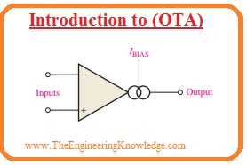
Introduction to operational Transconductance Amplifier (OTA)
- In the below figure you can see the symbolic representation of OTA. The double circle symbolic representation at the output end denotes the output current source which depends on the bias current.
- Similar to normal operational amplifiers the OTA comprises of 2 differential input terminals a large input impedance and large value of CMRR.
- Contrary to the conventional operational amplifier there is bias current input connection exists in the OTA large value impedance at an output and there is no fixed open-loop voltage gain.
What is Transconductance
- The transconductance of the electronic components is the ratio between the output current and input voltage.
- In the case of OTA voltage is input and current is output so the ratio between the output current and the input voltage is called gain.
- Resultantly the voltage to a current gain of OTA is called transconductance and denoted as gm.
Gm=Iout/Vin
- For OTA transconductance is depend on the constant K multiple with the bias current.
- The value of the constant depends on the inner circuit structure.
Gm=KIBIAS
- The output current is regulated through the input voltage and biases current as shown by the given formula.
Iout = gmVin = KIBIASVin
- The relation of transconductance and the bias current in OTA is significant for characteristics.
- The graphical representation in the below figure indicates this significant relation.
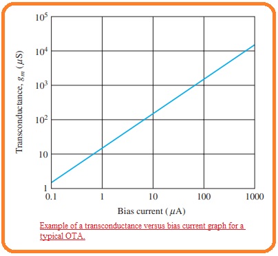
- Note that the transconductance rises in linear behavior with the bias current.
- The proportionality constant K is the line slope.
- In this condition, K is almost sixteen microseconds per microampere.
Basic OTA Circuits
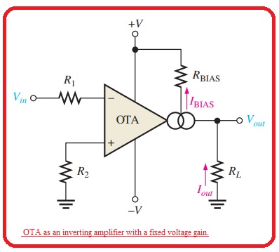
- The below figure indicates the OTA circuit representation that is shown as an inverting amplifier having a fixed value of voltage gain.
- The value of voltage gain is adjusted by the transconductance and the load resistance value is given as.
Vout = IoutRL
- If we divide both sides with Vin then we have.
Vout/Vin = (Iout/Vin) RL
- As Vout/Vin is the voltage gain and Iout/Iin is equal to gm.
Av = gmRL
- The transconductance of the amplifier is shown in below figure is found through the bias current that is set with the dc power source and the bias resistance RBias
- The most important factor of OTA is that the voltage gain can be regulated through the quantity of bias current.
- It can be created through the manual way as shown in the below figure with the use of variable resistance in series combination with the circuitry shown in the above figure.
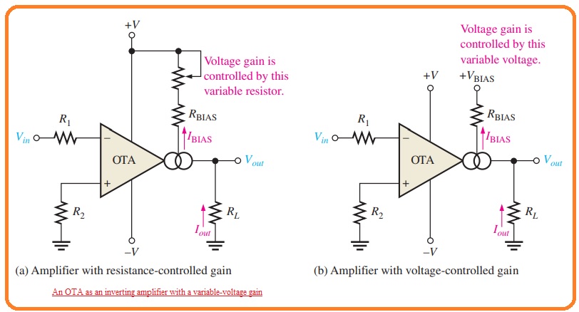
- Through varying the resistance we can generate a variation in which there is a change in transconductance.
- The change in the transconductance varies the voltage gain.
- The voltage gain can be regulated through the outerly given changeable voltage as shown in figure denoted as b.
- The change in the given bias voltage produces a variation in the bias current.
Types of OTA
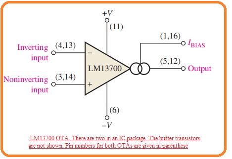
- The LM13700 is a certain category of OTA and operates as a representative component.
- The LM13700 is a dual-module casing comprised of 2 OTAs and buffer circuitries.
- The below figure indicates the pin arrangements with the use of a single OTA in the casing.
- The extreme dc voltage value is plus-minus eighteen volts and its transconductance parameters occur to the similar as shown in the above graph.
- In the case of LM13700, the bias current id find by this below formula.
IBIAS = (+VBIAS – (-V) – 1.4 V)/ RBIAS
- The 1.4 volts in this formula is due to inner circuitry where base-emitter junction and diode linked the outer Rbias through the negative voltage source.
- The positive bias voltage can be get through a positive power source.
OTA Applications
Amplitude Modulator
- The figure below shown define the OTA linked as an amplitude modulator. The voltage gain changes with the application of modulation voltage to bias input.
- When the constant value of amplitude input signal is given the amplitude of the output signal will change with respect to the modulation voltage at the bias input.
- The gain is dependent on the bias current and bias current is corespondent to the modulation voltage according to the given expression.
IBIAS = (VMOD – (-V) – 1.4 V)/ RBIAS
- This modulation process is shown in the above figure for large frequency sine wave input voltage and less frequency sin modulating voltage.
Schmitt Trigger
- The below figure indicates OTA in Schmitt trigger arrangments.
- The Schmitt trigger is a comparator having hysteresis where the input voltage has such value to run the module into its saturated condition.
- When the input voltage is larger than the specific threshold value or called trigger point the component changes state to one of its saturated output conditions.
- When the value of the input is less than the threshold value the component changes its state to saturated condition.
- For OTA Schmitt trigger the threshold level and is adjusted by the current with the use of resistance.
- The extreme output current in OTA is equal to the bias current.
- So in saturated output condition, the extreme positive voltage is IoutR1 and this voltage is a positive threshold value or upper trigger point.
- When the input voltage is larger than this value the output moves to its extreme negative voltage.
- That is -IoutR1 As Iout= IBIAS, the trigger points can be regulated through the bias current.
- The below figure defines this function.
What is the difference between OTA and an amplifier?
| Parameter | OTA (Operational Transconductance Amplifier) | Amplifier |
|---|---|---|
| Function | It transforms the voltage to current or current into voltage | It Amplifies the input signal either voltage or current without conversion. |
| Operation | it Works as a transconductance device. | it amplifies the input signal directly. |
| Input/Output | Normally comes with differential voltage input and current output | It comes with different input and output configurations like the voltage in/voltage out, current in/voltage out, etc.). |
| Applications | it used in analog signal processing and filtering circuits. | it is employed in different electronic devices audio systems and power amplifier |
| Feedback | it is mostly used outer feedback system to control the operation | Feedback can or not be employed based on the application. |
| Gain Control | it provides control over the transconductance (gm) which converts to gain control. | Gain can be varied through external components or internal settings. |
| Transconductance | With the use of differential input voltage to produce an output current | N/A (In some situations, amplifiers can have a transconductance stage, but not all.) |
| Typical Configuration | The two-stage differential amplifier (input stage and output stage). | Single-ended or differential amplifier configuration. |
Is the transconductance of an OTA dependent on a bias current?
Yes, the transconductance (gm) of an OTA is based on the bias current. Transconductance is a measurement of how much output current the OTA generates as a result of a variation in its input voltage. It characterizes the OTA’s features to transform the voltage to current.
In an OTA, the bias current is important in finding the transconductance. Normally increasing the bias current causes higher transconductance, while decreasing the bias current decreases transconductance. This equation is written as
gm = k * Ibias
Where:
- gm is the transconductance,
- k is a constant factor determined by the OTA’s design,
- Ibias is the bias current.
Through controlling the bias current engineers can set the OTA operation to transconductance, which helps them to handle OTA’s performance to certain application needs. It offers a way to get gain control and affect the OTA’s linearity, bandwidth, and other operating features. Though, the bias current must be carefully selected to balance the required performance with power use and thermal parameters.
FAQS
- What is an OTA?
An OTA is an electronic amplifier that uses a voltage-to-current converter to amplify signals. OTAs are mostly used in analog signal processing applications, like amplifiers, filters, and oscillators.
- How does an OTA work?
An OTA comes with a differential amplifier, a voltage-to-current converter, and a feedback system. The differential amplifier amplifies the input signal, and the voltage-to-current converter transforms the amplified signal into a current. The feedback network after that controls the gain of the amplifier.
- What are the advantages of OTAs?
- High input impedance: OTAs come with high input impedance, which means that they do not load the input signal.
- * Low output impedance: OTAs provide low output impedance, which shows that they can drive a large load.
- * Wide bandwidth: it comes with a wide bandwidth, which means that can amplify signals at different ranges of frequencies.* Low distortion: OTAs can amplify signals with less distortion.
- What are the disadvantages of OTAs?
- High power consumption: OTAs typically use larger power than other types of amplifiers.
- * Sensitivity to noise: They are sensitive to noise, which can redcues the performance of the amplifier.
- * Complex design: it can be more complicated to design than other amplifiers.
- What are some applications of OTAs?
- Filters
- Amplifiers
- Oscillators
- Comparators
- Data converters
- Analog-to-digital converters
- Digital-to-analog converters
That is a detailed post about Introduction to Operational Transconductance Amplifier (OTA) if you have any further query ask in the comments. Thanks for reading. Have a good day.