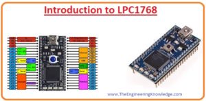
 Hello, readers welcome to another new interesting post. In today’s post, we will have a detailed look at Introduction to LPC1768. It is an ARM Cortex M3-based controller that is used in an embedded system for such projects that need less power. The core of this module which is Cortex-M3 which is the advanced level core provides different types of features such as debugging and support block integration of advanced level. It operates on the frequency of one hundred megahertz.
This device is incorporated with the three-stage pipeline and supports the Harvard architecture. In today’s post will discuss its pinout, application, features, and some other related parameters. So let’s get started with Introduction to LPC1768.
Introduction to LPC1768
- The LPC1768 is a type of microcontroller which generally used in different types of electronic and embedded system projects.
- This module comprises the inner flash memory unit of having space of five twelve kilobytes with a static random access memory of sixty-four kilobytes.
- Due to the large size of memory units, it is mostly preferred for such applications that need a large amount of data storage.
- It is also preferred for such applications that need a high speed of almost one hundred megahertz.
- It also comes with the transformation twelve-bit having an eight-channel analog to digital converter.
- This module comprises of ten-bit digital-to-analog converter, for controlling of motor has pulse width modulation, RTC is connected on this board which is compatible with the SPI, and I2C protocols.
- There are different types of inputs and outputs pinouts are exist on this board to do different operations.
- To store and transfer data through this board, is SD card socket is connected to this board.
- To regulate and transfer different categories of data and information between the computer and this board, it comprises of ethernet LAN 10/100megabyte connection.
- There is a high speed 2.0 connection of USB given at this board which operates as the sender and receiver of data.
- The best feature it provides is a 240 by 320 TFT touchscreen liquid crystal display and the resolution of this LCD is sixty-five thousand five hundred thirty-six bits.

Features of LPC1768
- These are some important features of this board which are discussed here with detail.
- It comprises of ARM-based Cortex-M3-based CPU operating at a frequency value of one hundred megahertz.
- It consists of five hundred twelve kilobyte space flash memory units.
- It comprises of thirteen by sixteen-kilo byte static random access memory unit.
- It consists of GPDMA having eight channels that are used to support SSP, I2S bus, UART, and A/D and D/A converters.
- It comprises of Ethernet MAC having RMII interfacing, with that has 2.0 high-speed USB port,.
- There are 4 UART connected on this board with that inner FIFO.
- It has CAN protocol with a two-byte controller having 2 channels.
- There is an SPI communication protocol, and serial and duplex communication is completed on it.
- There are 2 SSP controllers assembled on this board. This interfacing can be manipulated with the general-purpose DMA.
- There are seventy pinouts on this board,
- There is a bit analog to analog-to-digital converter is connected to this module. and four-timer included.
- It can operate in the voltage range of 2.4 to 3.3 volts.
- Its physical dimensions are in the range of (14 × 14 × 1.4) millimeters.
Serial Interfaces
- Ethernet MAC with RMII Interface
- Full-speed USB 2.0 Controller
- SPI
- I2S
- 4 UARTs
- 2-channel CAN Controller
- 2 SSP Controllers
- 3 I2C Interfaces
Peripherals
- 70 GPIO Pins
- 4-Timers
- Dedicated PWM Block
- Motor Control PWM
- 8-channel 12-bit ADC
- 10-bit DAC
- Quadrature Encoder Interface
- RTC
- WDT
Pins of LPC1768
LPC1768 comes with 70 pins and pins are configured in ports except for power, oscillator, and debug pins.
Five ports have 70 pinouts. That ports are Port 0 (P0), Port 1 (P1), Port 2 (P2), Port 3 (P3) and Port 4 (P4).
Each port can be 32-bit wider and comes with 32 pins maximum. But all ports not have 32 pins each has a different pin configuration
Port 0 – P0[30:0]
- Pins 12, 13, 14, and 31 in Port 0 do not exist.
Port 1 – P1[31:0]
- Pins 2, 3, 5, 6, 7, 11, 12, and 13 in Port 1 do not exist.
Port 2 – P2[13:0]
- Pins 14 to 31 in Port 2 do not have
Port 3 – P3[26:25]
- Pins 25 and 26 in Port 3 are available. Rest does not exist
Port 4 – P4[29:28]
- Pins 28 and 29 in Port 4 are exist. Rest not have

Applications of LPC1768
- These are some common applications of this module discussed here.
- It is used in different types of alarm systems.
- It is used in the lighting system,
- In industries circuits of different machines comprised this board,
- It is used for speed control of the motor.
Which architecture is used in the LPC1768 microcontroller?
- This processor comes with Harvard Architecture, which means comes with a separate instructions bus and data bus. Provide instruction and data access occurring at the same time that provides high performance.
How many ports are in LPC1768?
- LPC1768 MCU comes with 5 ports that are Port 0 (P0), Port 1 (P1), Port 2 (P2), Port 3 (P3), and Port 4 (P4).
- Each port is 32-bit wide and can come with 32 pins.
What is the PIN configuration of LPC1768?
- The pins of LPC1768 are configured in 5 ports that are 0 to 4.
- These pins are P0. 0 (group 0, pin 0) or (port 0, pin 0). For each single, there are 4 operating modes, GPIO(default), 1st alternate function, 2nd alternate function, and 3rd alternate function.
What is UART in LPC1768?
- UAER is a serial communication protocol where data is transferred in serial form bit by bit for a single time. Asynchronous serial communication is used for byte-based transmission.
What is the total number of bits to represent priority in LPC1768?
- LPC1768 comes with 32 priority levels that show that 4MSB bits are used for priority setting. The low priority number will have a high priority for interrupt. These bits are split into 2 groups that help to make sub-priority levels.
What are the timer registers in LPC1768?
- For LPC1768 there are 4 match registers for single timers. These match registers are used for resetting the timer, interrupting creation, for producing a timing signal.
How many registers are there in LPC1768?
- 5 registers for LPC1768 configured with GPIO functionality. They are GPIO pins register, GPIP direction control registers, port output clear register, fast port output set register and fast port pin value register.
That is a detailed post about LPC1768 if you have any further queries ask in the comments. thanks for reading.