 Hello, readers welcome to new post. Today we will learn Introduction to LM565 IC. This integrated circuit is created for different applications such as division of frequency multiplication of frequency and demodulation and is known as phase-locked loop IC. It has 2 main parts first one is a voltage-controlled oscillator and the second one is a phase detector.
This post will cover its basics pinouts features working and some other parameters. So let get startedwith Introduction to LM565 IC.
Introduction to LM565 IC
- The LM565 phase-locked IC used in general purpose applications and comprises of linear voltage controller oscillator and a stable circuit that helps for less distorted modulation. It also comes with a double-phase detector system that offers high-quality carrier suppression.
- For adjustment, the frequency of VCO exterior capacitor and resistance is used and a tuning range of ratio 10:1 can get with the use of a connected capacitor
- Its different features such as closed-loop system, bandwidth, and capture response speed can be regulated through use of resistor and capacitor
- Its loop can be damaged among the VCO and phase detector for placement of a digital frequency divider to get eh frequency multiplication
- Its operating temperatures range is minus fifty-five to one twenty-five centigrade.
Features of LM565 IC
- Its main features are discussed here
- Its highest power dissipation is fourteen hundred megawatts
- Its power supply current value is 12.5 mA
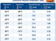
- The value of storage temperature is minus sixty-five to one fifty centigrade
- The highest operating temperatures is plus-minus five volts to plus-minus twelve volts
- The operating frequency for VCo is five hundred kilohertz
- It can operate t different values of input volts
- It gives the 0.2 percent linearity for demodulated output
Feature | Details |
| Power Supply Range | ±5V to ±12V |
| Maximum Operating Voltage | ±12V |
| Maximum Power Dissipation | 1400 mW |
| Maximum VCO | 500 kHz |
| Input Compatibility | TTL & DTL compatible |
| Hold-in Range | ±1% to above ±60% |
| Power Supply Current | 12.5 mA |
| Demodulated Output Linearity | 0.20% |
| Linear Triangle Signal Availability | Through in-phase zero crossings |
| Temperature Range | -55°C to +125°C |
| Temperature Range (Storage) | -65°C to +150°C |
| Frequency Stability of VCO | 200 ppm/°C |
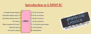
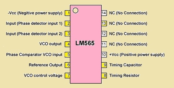
Pinout of LM565 IC
- Its main pinout is explained here
- Pin 1 -Vcc that used for negative power supply
- Pin 2 is used for phase detector
- Pin 3 is also a phase detector input
- Pin 4 VCO output pin
- Pin 5 is input of the phase detector
- Pin 6 is the inner amplifier reference o/p
- Pin 7 used for VCO volts control
- Pin 8 is resistance for the free-running frequency of VCO
- Pin 9 Timing capacitor for VCO
- Pin +Vcc Here positive supply given
- Pin 11 to 14 are not in use
| Pin | Name |
| 1 | -Vcc |
| 2 | Input |
| 3 | Input |
| 4 | VCO output |
| 5 | Phase comparator VCO input |
| 6 | Reference output |
| 7 | VCO control voltage |
| 8 | Timing Resistor |
| 9 | Timing Capacitor |
| 10 | +Vcc |
| 11 | NC |
| 12 | NC |
| 13 | NC |
| 14 | NC |
 LM565 Alternatives
- MC1648
- MAX2880
- 74HCT9046A
- 74LV4046A
LM565 IC Applications
- Common applications of LM565 are explained here
- it used in coherent demodulators
- Used for generation of signal
- Used in telemetry receivers
- Used in SCA demodulators
- Used for multiplication and division of frequency
- Used in tone decoders
- Used in the frequency synthesizer
- Used in modems
- Used for data and type synchronization
- Used for FSK modulation and FM modulation
Working of LM565
- Here we have made a block diagram of LM565 for understanding of working.
- The understanding of the inner design of module Pine 3 is grounded as a reference point, and Pin 2 gets input signals.
- These signals interact with feedback from the voltage controller oscillator at the phase detector, which makes a comparison of frequency and phase.
- If they are in the same phase, the detector provides zero output with stability.
- It does not match the phase detector and produces a voltage that is amplified for setting the VCO frequency.
- It is good for configuring the input signal, and VCO provides synchronization and increases signal stability.
- The VCO produces a signal that has a frequency configured with an external component at pin 8 and pin 9 without input signals.
- If an input signal exists, VCO set frequency for matching provides accurate frequency regulation.
- This work is used for communications systems and audio synthesizers.
Read also
- LM324 – Single Supply Quad Operational Amplifiers worksheet
- 2022 P Wilma Mankiller Quarter Worth | Learn the Value of This Coin
- Difference between LM741 and LM358
- Introduction to LM340T5
- Introduction to LM386 Audio Amplifier IC
That is all about the LM565 IC all details has explained if you have any further query ask in the comments. Thanks for reading have a nice day