 Hello, readers welcome to the new post. In this post, we will discuss the Introduction to LM358. LM358 is low power consuming less expensive dual-channel operational amplifier integrated circuit. It is constructed to operate through a single power supply at different values of volts. It standard operational amplifier and can be used for different electronic projects. It is small-size integrated circuitry.
Its small size and less cost structure make it useful for different applications. In this post, we will discuss its working pinout and some other related parameters. So let’s get started Introduction to LM358
Introduction to LM358
- The LM358 is a dual-operational amplifier integrated circuit that comes with two operational amplifiers having one common power supply.
- It is like the half structure of the LM324 operational amplifier that has four operations amplifiers with a mutual power supply.
- The input volts are the same as the power supply voltage. The default input offset voltage is less than two millivolts.
- The normal input current is about five hundred microamperes not depending on the supply volts value and the highest current of seven hundred microamperes.
- The operating temperature lies zero to seventy centigrade and the highest junction temperature can be about one fifty centigrade.
- The structure of this amplifier consists of active filters and transducer amplifiers.
LM358 Dual Op-Amp IC Features
- The main features of LM358 are explained here
- It comes in different packaging such as DSBGA, PDIP, SOIC, CDIP
- its soldering pin temperature is about two sixty centigrade
- The operating temperature is about zero to seventy centigrade
- It comes with short circuit protection output
- It has a single supply that can operate two operational amplifiers
- its low supply current is 700uA
- It has two operational amplifiers in one packaging
- It has different power supply values
- Its single supply volts are three to thirty volts and double supply volts are ±1.5V to ±16V
Specifications of LM358
| Features | Details |
| Operating Voltage Range | 2.0 Vdc to 36 Vdc |
| Split Supply Range | ±1.0 Vdc to ±18 Vdc |
| Current Consumption | 0.4 mA |
| Input Bias Current | 25 nA |
| Output Voltage Compatibility | TTL, MOS, DTL, ECL, and CMOS Logic Levels |
| ESD Clamps | on Inputs for increased Durability |
| Automotive Applications | Prefix “NCV”, supported AEC−Q100 and PPAP Standards |
| Environmental Compliance | Pb-Free, Halogen-Free, BFR-Free, RoHS Compliant |
| Input Offset Current | 5.0 nA |
| Input Offset Voltage | 5.0 mV |
| Input Common Mode Range | upto Ground Level |
| Differential Input Voltage Range | same as Power Supply Voltage |
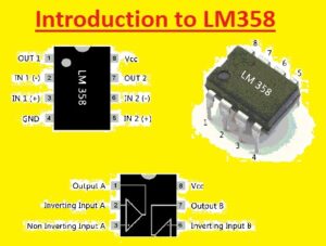
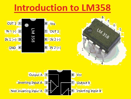
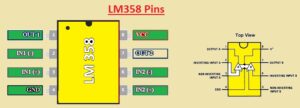
LM358 Pins
- It comes with eight pinouts that is listed here
- Pin 1 is the output of operational amplifier one
- Pin 2 is the negative or inverting input of the first operational amplifier
- Pin 3 is the positive or non-inverting input of the first operational amplifier
- Pin 4 is the ground pin
- Pin 5 is the positive inverting input of the second operational amplifier
- Pin 6 is the negative input of the second operational amplifier
- Pin 7 is the output of the second amplifier
- pin 8 is the power supply pinout
Simple Shock alarm circuit using LM358
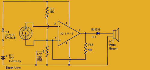
- The shock alarm circuitry is commonly used in vehicles and created through the use of LM358. It operates as an anti-theft alarm in vehicles. It uses piezoelectric sensors that operate as shock sensor which is mounted on the door that we have to guard
- In the below circuitry, LM348 is configured by inverting the Schmitt trigger. The R1 resistance adjusts the threshold voltage of the circuit. That operates as feedback resistance
- When the piezoelectric sensor does not activate the output though the piezoelectric sensor has a low value at this instant input is high and operates the Schmitt trigger in resulting sound produced through the buzzer
- The buzzer remains in operating condition for some time intervals when vibration is not connected. it is that inverting input has a small effect when LM358 I is triggered and the condition cannot be inverted easily. So there must be a strong connection between the sensor at the surface where it is installed.
LM358 IC Advantages
- It does not need the dual power supply for an operation which is the main benefit
- it comes with two operational amplifiers installed in its desing
- it has the ability to direct the sense of the ground and output
- It is best operated through the logic method
- It drains power accurately for the operation of the battery
LM358 IC Applications
- It used a dc gain block circuitry
- It is the main part of shock alarm circuitry and dark sensor circuits
- It used in transducer amplifier operation
- It used in the current loop transmitter for four to twenty milliampere
- It used in active filter
- it used as signal conditioning circuits
LM358 vs LM393
| Features | LM358 | LM393 |
| Supply Voltage | 32V, +/-16V | 36V, +/-18V |
| Large Signal Voltage Gain | 100V/mV typ. | 200V/mV typ. |
| Bandwidth | 1MHz | Not specified |
| Differential Input Voltage | 32V | 36V |
| Input Offset Voltage | 3mV max. | 5mV max. |
| Input Bias Current | 100nA max. | 250nA max. |
| Input Common Mode Range | 0V to V+ – 2V | 0V to V+ – 1.5V |
LM358 Operating Principle
- The 8th pin of the LM358 is the main power supply input pin. The comparator function of the LM358 input voltage value is 3 to 32 volts.
- In the use of an operational amplifier as an LM358, the voltage supply value is ±1.5 ±1.5V to ±16 V.
- There are 2 operational amplifiers configured in LM358 where the input of the first amplifier is at pin 2 and the output is taken at pin 1.
- For using the 2nd amplifier input of the amplifier, it is given at pins 5 and 6, and the output is taken out from pin 7.
- To make a comparison of two signals, give one signal at pin 2 and the other at pin 3. A voltage of pin 2 compared with pin 3 and voltage of pin 3 compared to pin 5 based on 2 outputs.
- If the input of non-inverting input A+ given at pin 3 is larger as compared to the input of inverting input A- of pin 2, the output is high.
- If the input of non-inverting input B+ of pin 5 is larger as compared to the input of inverting input B- of pin 6, the output of operational amplifier B is high.
- If non-inverting input A+ for pin 3 is low as compared to inverting input A- pin 2. Output is low.
LM358 Equivalents
- LM358A
- LM358W
- LM358E
- LM358-N
FAQ
Are LM358 and LM393 interchangeable?
- NO Both are different components: the LM358 is an operational amplifier that comes with a push-pull output stage, and the LM393 is a comparator that has an open collector output that needs an external pull-up resistor. They are made to be used for different applications and not used as replacements.
Are the differences between a comparator and an operational amplifier the same?
- The operational amplifiers and comparators are different. The operational amplifiers used for amplification of small voltage differences exist between inputs working with linear range. The comparator is used for the comparison of two input voltages and gives high or low output according to the high input value.
- Comparators are used for handling higher voltage differences at input than op-amps.
Is the LM358 used as an audio amplifier?
- LM358 is not good to use for amplification circuits. Its inner structure does not support high-quality audio processing and restricts the use of audio circuits.
Can the LM393 replace the LM358?
- No, they are different. The LM393 is a comparator, and the LM358 is an operational amplifier. Both have different functions and are not replaced.
What is the main difference between the LM393 and the LM339?
- The basic difference is the number of channels and package size. The LM393 is a dual-channel comparator with an 8-pin SOP package, and the LM339 is a quad-channel comparator that comes with a 14-pin SOP package. Both have the same working, but the channel count and design are different.
That is all about the LM358 all details have been explained if you have any questions ask them here


