
 Hello, readers welcome to the new post. Today we will discuss Introduction to Copper Core PCB. The Metal core PCB board is also called a thermal board or metal-backed board. it is a type of PCB that uses metallic material at the base to spread the heat of the board. Thick metals like aluminum or copper is applied on one side of the board. The metallic core can be positioned either mid, backside, or any other side of the board. The motive of the core created through MCPCB is to dissipate heat by spreading away from the components connected to the PCB. The metallic base of metal core PCB is an alternative of Fr4 or CEM3 boards.
There are three main types of metal core PCB like aluminum PCB, copper core PCB, and iron-based PCB. Since high-power electronic components are now very commonly employed in the industry in different devices so they need a high level of PCB heat dissipation, so the demand for metal core PCB also increasing but mostly copper-based PCB. That is mostly used in applications where high-power and high-frequency PCB design is needed. Since copper core PCB has a good feature of dissipating heat during circuit operation. In this post, we will have a detailed look at copper core PCB and also learn how you can get copper core PCB from JLCPCB. So let’s get started
What is copper-based PCB?
- Copper core PCB is a type of Metal core PCB that uses copper as core material. It is a costly type of metal core board and provides good heat dissipation than other metallic types iron core and aluminum PCB.
- It is part of high-frequency designs, and applications here high and low temperature exists with that are also used in communication devices.
- The high demand for current-carrying copper-based PCB layers so thick copper of 35um to 280um layer is created. the use of a thermal conductively insulating layer has a good effect on the copper-based board.
- Thermal conductivity is normally created through the use of aluminum oxide and silicon powder also with polymer-filled epoxy resin.
- The main benefits of the copper core board are low thermal resistance with 0.15, good viscoplastic property, and thermal aging control.
- The copper substrate has great importance of copper core PCB board in that is heat dissipation, shielding, and grounding.
- With all these features it must have high thermal conductivity, application of general mechanical techniques, like drilling, punching, and cutting
copper based PCB Types
- The main types of copper core PCB are listed here
- Immersion gold copper-based PCB
- Silver-plating copper-based PCB
- Hot air soldering leveling (HASL) copper-based PCB
- Anti-oxidation copper-based PCB
Difference between Aluminum and Copper Core PCB
- These two boards are some in some features and functions but have some differences. That are listed here
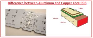
Cost of Metal
- it is the most important fact during the design and construction of PCB. Copper is more expensive than aluminum due to its rare structure. For applications where is budget has main consideration aluminum PCB prefer then copper board
Thermal Conductivity
- Therm conductivity is the rate at which heat is transferred in metals, aluminum provides a high-speed heat transfer than copper. Copper boards performed well during high temperatures and high power operations.
Electrical Conductivity
- Aluminum and copper are good conductors of electricity but the accurate degree of these metals is different for these two metals. For electrical conductivity, aspect copper is good than aluminum and is proffered for PCB designs.
Electrical Resistance
- Resistance is a significant aspect of the design of PCB since it has a great impact on the operation and stability of comments attached on the board. The density of cooper is higher than aluminum that results in less resistance than aluminum so copper is preferred for circuits where high current and less resistance needed
Weight
- As the density per unit area for copper is larger than copper the weight of the copper board is high than the aluminum board for the same design configuration. For projects where lightweight is the main objective then aluminum is used. But for projects where weight is not an issue there copper applied
| Feature | Aluminum Core PCB | Copper Core PCB |
|---|---|---|
| Thermal conductivity | 160-200 W/m·K | 380-400 W/m·K |
| Weight | Lighter | Heavier |
| Cost | Less costly | More costly |
| Manufacturing difficulty | Less difficult | More difficult |
| Number of layers | Suitable for single-layer PCBs | Best for multiple-layer PCBs |
| Resistance | Higher resistance | Lower resistance |
| Heat dissipation | Good heat dissipation | Excellent heat dissipation |
| Applications | Low-power applications, light-weight applications | High-power applications, applications with strict thermal requirements |
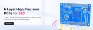
JLCPCB Direct Heatsink Copper-Cored PCBs
- JLCPCB is PCB supplies that provide the PCB bases services with great quality and economical charges. JLCPCB Established in 2006, JLCPCB is at the forefront of the PCB industry. With more than 15 years of continuous innovation and improvement based on customer needs, they have grown rapidly to become the world’s leading PCB manufacturer, providing rapid production of highly reliable and cost-effective PCBs and creating the best customer experience in the industry.
- JLCPCB Direct Heatsink Copper-Cored PCB has been officially launched! As you already know that JLCPCB launched Aluminum PCB in 2021 which got lots of praise and support. So after one year, the ward hard JLCPCB is confident to introduce Direct Heatsink Copper PCB that has good heat transfer and preferable high power components. The motive of JLCPCB to provide a cost-effective solution to their customers leads to copper PCB with a promise to give the best benefits to every customer
- Some features of the regular copper base and direct heatsink copper base of JLCPCB are here
- The direct heatsink feature of JLCPCB provides good cooling for high-power applications like COB LED and switching regulators. In the figure, you can see that This is done by making the heatsink pads as raised platforms from the copper PCB base so that heat transfer is not affected by the presence of any insulation.
- Conversely, heat transfer on conventional printed circuit boards with a metal core must pass through an insulating layer with a much lower thermal conductivity than copper.
- These charges not have additional steps, as with flexible boards and multiple layers, so it is not getting from each manufacturer. Regular aluminum and copper core boards are commonly available since they are created in the same fashion as single-layer FR-4 PCB
- Direct heatsink pads can be rectangle shape or polygonal with at least 1mm wide in any side. They cannot be attached to regular pads and traces but their traces need it is used o make all of them with a direct heatsink-like raised platform on a copper base
- Plating is not possible because the holes in the FR-4 layer are not plated. The minimum drill diameter is 1 mm; the minimum slot width is 1.6 mm. OSP surface treatment (organic solderability) is used. Panels are accepted, but only V-notch is available.
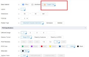
How to Order JLCPCB Copper PCB
- With choose of Direct Heatsink Copper for the base, a material drawing must be attached to show which part of copper has to create through the direct heatsink/ connected with the base. It is recommended to choose the accurate Production file option so that before production you can assure that your directions have been accurately understood
- To make technology innovation easy that JLCPCB always makes sure. JLCPCB keeps improving to get more advanced boards to fulfill the user’s demands all over the world. To be the best platform for smart PCB manufacturing, JLCPCB is always on the way!
copper based PCB Advantages
- As compared to aluminum board copper core PCB provides good thermal conductivity normally two times than aluminum. High conductivity results in high heat dissipation.
- The base of copper PCB can be plated through the hole but the aluminum base not. The copper base on the board can be etched through high drawing, the boss shape gets through processing, which is a good option for components, components of projects can be directly connected on the surface which provides good effects for grounding and heat dissipation.
- Copper has modules of elasticity of about 121000MPA and aluminum has 72000MPa and the shrinkage features of copper-based boards are less than aluminum.
Copper-based PCB Features
- It has the ability to withstand thermal aging
- It provides the good viscoplastic features
- Its mechanical strength is high
- Non-magnetic behavior shown
- It has good stability
Rules of Copper Core PCB Desing
- The diameter for minimum drilling is about 0.4mm due to the thickness of the copper base, the copper foil thickness can direct the line width and spacing, if copper is thicker it will be required wider line width and larger least spacing
Thermoelectric separation copper-based PCB
- For the circuit layer circuit parts is not similar to the thermal layer of the substrate, and a portion of the thermal layer is connected with parts of lamp head heat dissipation to get the best heat dissipation and less thermal resistance.
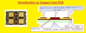
Metal core PCBs Layers
The basic structure of a metal core PCB (MCPCB) comes with these layers
- Solder mask layer: This layer is a thin coating of solder resist that is applied on the copper layer to protect it from oxidation and to avoid solder from bridging between traces.
- Circuit layer: This layer is created with copper and comes with the conductive traces that created the electronic circuit.
- Copper layer: These layers are created with copper and are thick than the circuit layer. It offers more heat dissipation and mechanical strength to the PCB board.
- Dielectric layer: This layer is created with material with high thermal conductivity, like FR4 or PTFE. It isolates the copper layers from each other and provides electrical insulation.
- Metal core layer: it is created with metal, like aluminum or copper. It offers heat dissipation and mechanical strength to the PCB board.
Different types of metal core PCBs
different types of metal core PCBs are explained here
- Single-layer MCPCB: it has a single copper layer on top of a metal core layer. It is a common type of MCPCB and is used for simple applications, like LED lighting and power supplies.
- Double-layer MCPCB: This type has two copper layers isolated by a dielectric layer. It is used for complicated applications that need good heat dissipation, like RF amplifiers and power converters.
- Multi-layer MCPCB: These boards have multiple copper layers separated by dielectric layers. It is employed for the most complicated applications and can offer the best heat dissipation and mechanical strength. Multi-layer MCPCBs are mostly used in applications like aerospace and defense.
MCPCBs metal base Materials
The most common metal base materials used for MCPCBs (Metal Core Printed Circuit Boards) explained
- Aluminum: Aluminum is a very commonly used metal for MCPCBs since it comes with a good balance of thermal conductivity, prices, and weight. It can be easily managed on machines and work with them
- Copper: Copper provides good thermal conductivity than aluminum, but it is also the most expensive. Copper MCPCBs are used in applications where heat dissipation is important, like LED lighting and power electronics.
- Steel: Steel is less commonly used for MCPCBs than aluminum or copper, but it can be a good solution for applications where high strength and rigidity are needed. Steel MCPCBs are also often used in harsh conditions, like those with high temperatures or corrosive chemicals.
- Brass: Brass is a good conductor of heat, but it is also more costly than aluminum. It is used in applications where corrosion resistance is important.
- Titanium: Titanium is a strong and less-weight metal with good thermal conductivity. It is used in aviation and defense applications.
- Inconel: Inconel is a nickel-chromium alloy with good corrosion resistance and high-temperature performance. It is often used in applications where these features are important, like the oil and gas industry.
Faqs
- What is an MCPCB?
An MCPCB is a metal core printed circuit board. It is created with a metal core, a copper layer, and a solder mask. The metal core offers heat dissipation, while the copper layer carries the electrical current. The solder mask protects the copper layer from oxidation.
- What are the benefits of using MCPCBs?
MCPCBs provdies different benefits than traditional PCBs,like:
Improved heat dissipation: The metal core in an MCPCB helps to dissipate heat more effectively than a convetional PCB, which can extend the life of the LED and improve its performance.
Increased reliability: MCPCBs are reliable than traditional boards since they are less likely to fail due to heat damage. * Decreases size and weight: MCPCBs are small size and lighter than other boards, which can save space and weight in electronic devices.
Improved aesthetics: MCPCBs can be created to look more aesthetically pleasing than other PCBs, which can be good in some applications.
- What are the different types of MCPCBs?
There are 2 main types of MCPCBs:
Direct-mount MCPCBs: These MCPCBs are directly mounted to the LED. They are the simplest MCPCB and are easy to solder.
Heatsink MCPCBs: These MCPCBs have a heatsink connected them. The heatsink helps to dissipate heat even more effectively than a direct-mounted MCPCB.
- How do you choose the right MCPCB for your application?
When selecting an MCPCB for your application, you needed to consider the these paramters:
The type of LED you are using: The MCPCB needs to be supported with the type of LED you are using.
The amount of heat the LED generates: The MCPCB needed to be able to dissipate enough heat to avoids the LED from overheating.
The size and weight of the MCPCB: The MCPCB needed to be the accurate size and weight for your application.
- How do you mount an MCPCB?
There are 2 main methods to mount an MCPCB:
Direct mounting: This is the simplest method to mount an MCPCB. You must solder the MCPCB directly to the LED. Heatsink mounting: it is complicated methods to mount an MCPCB, but it offers good heat dissipation.
- How do you solder an MCPCB?
To solder an MCPCB, there is need to use a soldering iron with a fine tip.We also need to use solder that is supported with the metal core of the MCPCB. When you have the soldering iron and solder, can follow these steps to solder the MCPCB:
1. Clean the surfaces of the MCPCB and the LED with isopropyl alcohol.
2. Apply flux to the surfaces of the MCPCB and the LED.
3. Heat the MCPCB and the LED until they are hot enough to melt the solder.
4. Apply solder to the joint between the MCPCB and the LED.
5. Allow the solder to cool.
- How do you troubleshoot MCPCB problems?
If you are having issues with an MCPCB, there are some things to check: Ensure that the MCPCB is supported with the LED you are using. Confirm that the MCPCB is mounted accuratly.
Ensure that the MCPCB is not overheating. Check the solder joints for any cracks or breaks.
If you have monitired all of these things and you are still having issues, you can have to replace the MCPCB.
- Where can I buy MCPCBs?
MCPCBs can be buy from a number of online retailers, as well as from some electronics distributors.
- How much do MCPCBs cost?
The cost of MCPCBs changes based on the size, type, and manufacturer. Thouhg, MCPCBs are typically more costly than traditional PCBs.
- What are the future trends for MCPCBs?
The future trends for MCPCBs are very good. As LED technology continues to grow, MCPCBs will become good important for offering heat dissipation and increases the performance of LEDs. MCPCBs are also becoming affordable, which will make them good accessible to a different range of applications.
That is all about the Introduction to Copper Core PCB all details has explained. If you have any queries ask here. Thanks for reading have a nice day