
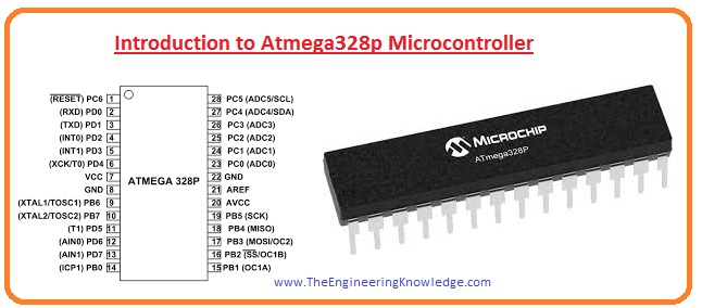
 Hi readers I hope you all are enjoying your life. In today’s post, we will have a detailed look at Introduction to Atmega328p Microcontroller. This category of the microcontroller is a high speed and less power consuming module. This MCU is eight bits based on AVR (Audio/Video Receiver) RISC (Reduced-instruction-set Computing).
Due to usage in boards, it is a commonly used ACR microcontroller. In today’s post, we will have a detailed look at its working, application, operation, and some related factors. So let’s get started with Introduction to Atmega328p Microcontroller.
Introduction to Atmega328p Microcontroller
- The Atmega328P is a highly reliable microchip eight-bit AVR controller. It comprises of thirty-two-kilo bytes flash memory with the read and writes features.
- These modules also comprise one thousand twenty-four byte EEPROM (electrically erasable programmable read-only memory), two-kilobyte static random access memory, twenty-three inputs, and outputs lines.
- It also has thirty-two registers, 3 flexible timers, inner and exterior interrupts, series programmable USART.
- With all these, it has Two-wire series interfacing through which data is transmitted in bytes, SPI port, six-channel ten-bit analog to digital converters, and has 5 power-saving modes.
- Its operating voltage is 1.8 volts to 5.5 volts.
- With the use of a single clock cycle, this module gets throughputs reaching one MIPS in one megahertz.
Features of Atmega328p
- The most common features of Atmega328p are described here with the details.
- This module has eight-bit AVR central processing unit.
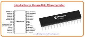
- There are twenty-eight pinouts exits in this module.
- The voltage over which this module operates is plus 1.8 Volts to +5.5 volts.
- There are twenty-three programmable inputs outputs pinouts are exits in this module
- The main communication interfacing in this module is master-slave SPI series interfacing which performs through the 17, 18 19 pinouts. To programmed MCU programmable USART is exited at 2, and 3 pinouts. For connection of external devices, 2 wire interfacing through pinout 27 and 28 is done.
- the analog to digital converter of six-channel and ten-bit resolution is used,
- it has an analog comparator at pinouts 12 and 13.
- There is a six pulse width modulation channel it has.
- There is three external oscillators it has first had frequency value from zero to four megahertz and operating voltage of 1.8 volts to 5.5 volts second has zero to the ten-hertz frequency and 2.7 volts to 5.5 volts operating voltage and third has a frequency of zero to twenty megahertz and operating voltage of 4.5 volts to 5.5 volts.
- It has an inner oscillator of eight mage hertz.
- It has programmable flash memory which is 32 kilobytes.
- Its central processing unit speed is one Million Instructions Per Second for one megahertz.
- It has two kilobytes of inner static RAM.
- It has one kilobyte EEPROM
- Its operating temperature is minus forty to plus one zero five centigrade.
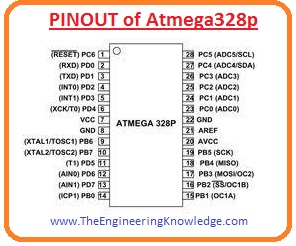
PINOUT of Atmega328p
- There are twenty-eight pinouts exits in Atmega328p which are discussed here with the details.
PC6
- It is six pinouts of port C. It is reset pinout and can be used as input and output when RSTDISBL get programming,
PD0
- It is zero pinouts of port D. It is input data transmission pinout for USART and for series communication interface.
PD1
- It is the first pinout of port D. it used as output for SART.
PD2
- it is two pinouts of port D.And used as exterior interrupt zero.
PD3
- It is the third pinout of port D.
PD4
- it is the fourth pinout of Port D.
VCC
- This pinout is linked with the positive voltage.
GND
- It is linked to the ground terminal.
PB6
- it is six pinouts of port B and used to get exterior clock input.
PB7
- It is seven pinouts of port B and operates as a chip clock oscillator pin.
PD5
- It is the fifth pinout of port D and here the external clock counter is connected.
PD6
- It is six pinouts of port D.
PD7
- it is the seventh pinout of port D.
PB0
- It is zero pinouts of port B.
PB1
- it is the first pinout of port B,
PB2
- It is the second pinout of port B and is low when MCU operating as a slave.
PB3
- It is third pinout of port B when MCU is operating as slave data can be received through this pinout.
PB4
- This pin is used to send data from the controller when it operating as a slave.
PB5
- This pinout is used to transfer of data between MCU and external devices linked with the controller.
AVCC
- it is a power pinout for external analog to digital converter.
AREF
- It is an analog reference pinout for analog to digital converter.
GND
- It is ground pinout.
PC0
- It is zero pinouts of port c.
PC1
- First pinout of port C.
PC2
- Second pinout of port C.
PC3
- The third pinout of port C.
PC4
- Further pinout of port c.
PC5
- It is the fifth pinout of port C.
Applications of Atmega328p
- These are some applications of Atmega328p which are mentioned here.
- Atmega328p is used in different types of Arduino such as Arduino Uno, Arduino nano, Arduino micro.
- It uses different types of control systems used in industries.
- It also employed in the power regulation system.
- It used in the digital processing of data.
- It used in the control of motor speed.
So friends that are detailed post about Atmega328p if you have any further query ask in comments. Thanks for reading. Have a good day,