 Hi, readers welcome to the new post. In today’s tutorial, we will have a detailed look at Introduction to 8051 Microcontroller. The first time this microcontroller was created by the Intel in 1980. Its structure is based on Harvard Architecture and was created to be employed in the embedded system. Firstly it was manufactured with the use of the NMOS technique but this technique was expensive and uses a lot of power so Intel replaced this technique with the CMOS and created a new version that has the letter C for the difference from the previous controller and is written as 80C51.
So the controllers that are currently created and used in different engineering simulations use less power due to creation through the CMOS technique. There are 2 types of Buses used in this module first is for program and second for data transmission. So it consists of 2 storage spaces used for to store programs and data of sixty-four-kilo bytes. In today’s post, we will have a detailed look at its working, operation, pinouts, and some other related factors. So let’s get started with Introduction to 8051 Microcontroller.
Introduction to 8051 Microcontroller
- The 8051 Microcontroller is Ic which is incorporated with forty pinouts and has a central processing unit with other devices such as random access memory, and read-only memory.
- The space of ROM used in this module is four kilobytes and the space of ROM is one twenty byte with that it has two sixteen-bit timers,
- There are four parallel eight-bit port exits in this device which can be programmed according to the requirements of the project.
- The crystal oscillator is assembled on this board having a frequency of twelve megahertz.
- Previous models of this module used assembly language but the new version used C, and javascript languages.
- Like other controllers, these modules are not created through the NMOS technique but constructed with the CMOS.
- The common packaging in which it exits is DIP, forty-four lead TQFP, forty-four lead PLCC.
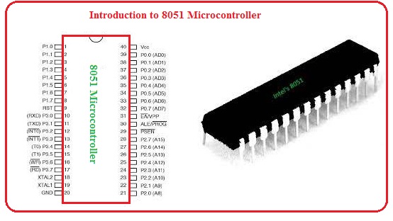
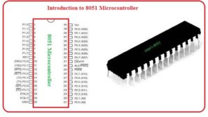
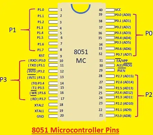
Pinout of 8051 Microcontroller
- These are forty pinouts of 8051 Microcontrollers which are discussed here.
Pinout 40
- it is denoted as Vcc and five volts are given to this pinout.
Pinouts 32 to 39
- these pinouts belong to Port Zero and operate as input and output pinouts.
Pinout 31
- This pinout is used to enable or disable the exterior memory interfacing.
Pinout 30
- it is ALE or aka address latch that enables pinout which used to demultiplex the address-data signal at port zero.
Pinout 29
- It is PSEN pinout which used to read signals from the exterior memory unit.
Pinout 21 to 28
- This group of pinout belongs to port 2 and used as input and output.
Pinout 20
- It is Vss and used for the ground connection.
Pinout 18,19
- Through these 2 pins, the exterior clock is given to the module.
Pinout 10 to 17
- This group of pinout belongs to port 3.
Pinout 9
- It is reset pinout
Pinout 1 to 8
- These pinouts belong to the port one and operate as input and output pins.
8051 Microcontroller Ports
- There total 4 ports exist in the 8051 microcontroller and each comes with 8 pins.
Port 0
- In this port, pins are from 32 to 39 and are two-direction pins
Port 1.
- This port comes with Pin 1 to 8 and they are also bidirectional
Port 2.
- In this port, pins are from 21 to 28 and used as higher addresses or data buses.
Port 3.
- This port has pins from 10 to 17

8051 Microcontroller Structure
- In the below figure inner structure of 8051 is shown let’s discuss it with detail.
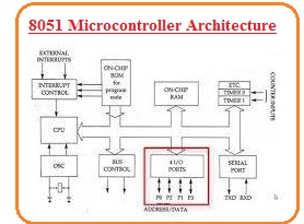
CPU
- The central processing unit is the brain of the controller. All tasks performed by the controller is managed through this part. OVer operation of CPU, there is no influence of the user. The interpretation of the information stored in the read-only memory is done through this part and execute the specified operation.
- All types of registers used in the controller are controlled by the CPU.
Interrupts:
- In some cases, we need to stop the continued process and execute the coming process for these interrupts to be used.
- There are 5 types of interrupts used in the structure of the 8051 controllers which are INT0, TF0, INT1, TF1, R1/T1.
- These interrupts create some time intervals in the execution of the main program. TF0 and TF1 are timers interrupts and INT0 and INT1 are exterior interrupts. While R1/T1 is a serial port interrupt.
Memory Unit
- Above we discussed that CPU is used for the execution of different commands. To store these commands memory is used. there are 2 types of memory units used in the controller Random access memory and read-only memory.
- The storing space of read-only memory is four-kilo bytes and the storage of random access memory is one twenty bytes.
- The instruction stored in the ROM is called code. ROM is non-volatile memory it stores data for large time intervals when the power applied is off.
- Random-access memory is a volatile memory that retains data for a short time and it needed a regular power supply for data storage.
RAM
- 128-byte RAM for data storage.
ROM
- 4KB ROM is available for program storage.
Serial Port
- For serial communication in the 8051 controllers, the UART port is used. It operates in 2 ways can send and receive data.
- There are 3 pinout exits in the serial port transmitter, receiver, and ground.
8051 Timers and Counters
- It has two timer pins that are T0 and T1. These timers help to produce delays for certain timers.
- It comes with two 16-bit timers registers that are T0 (TH0 & TL0) and T1 (TH1 & TL1),
Features of 8051 Microcontroller
- It comes with a ROM of 4KB bytes on-chip
- It has RAM of 128 bytes on-chip with 4 register banks
- it has128 user-defined software flags, 8-bit bidirectional data bus also configured with 16-bit unidirectional address bus
- It has 32 general-purpose registers of 8-bit. 16-bit timers and 3 internal and 2 external Interrupts
- Four 8-bit ports it has with 16-bit program counter and data pointer
Applications of 8051 Microcontroller
- These are some important applications of 8051 microcontrollers.
- It used in different types of industrial projects.
- To control the different processes it used.
- It also exits in different electronic devices such as Tv, VCR, video games.
- It has security circuits and Automattic operating devices.
- It is used in different temperature detection devices.
- The parking indicator comprises this module.
- In a fire detector, this module is used.
- Speed control of dc motor can be done with this device.
Difference between 8051 and PIC
| Feature | 8051 | PIC |
| Structure | 8-bit | 8-bit or 16-bit |
| CPU Speed | 33 MHz | 32 MHz |
Interrupt handling | Simple and limited | complex |
Development tools | available and matur | Growing |
| Cost | Lower | Lower |
Power Use | High | Low |
Instruction Set | Limited | complex |
On-chip memory | Limited | larger on-chip memory |
On-chip peripherals | Limited | diverse on-chip peripherals |
| Bus | 8 bit for standard core. | 8-bit/16-bit/32-bit |
| Speed | slower | Fast |
| Architecture | Von Neumann architecture. | Harvard architecture. |
| Memory types | ROM, SRAM, FLASH memory. | SRAM, FLASH memory. |
communication protocols. | UART, USART, SPI, I2C | PIC, LIN, UART, Ethernet, I2S, SPI USART, CAN, |
| clock | 12 clock per instruction cycle. | 4 clock per instruction cycle. |
| Types | AT89S52, AT89C1051, AT89C51, AT89C52, AT89S51, AT89C2051. | PIC18fXX8, PIC32MXX. PIC16f88X, |
8051 Family Members
| Feature | 8051 | 8052 | 8031 |
| ROM(bytes) | 4K | 8K | 0K |
| Serial port | 1 | 1 | 1 |
| Interrupt sources | 6 | 8 | 6 |
| RAM(bytes) | 128 | 256 | 128 |
| Timers | 2 | 3 | 2 |
| I/O pins | 32 | 32 | 32 |
8051 vs AVR Microcontrollers
| Features | 8051 | AVR |
| Architecture | 8-bit | 8-bit or 32-bit |
| CPU Speed | 33 MHz | 20 MHz |
On-chip peripherals | Limited | More |
Interrupt handling | Simple | More complex |
| Cost | Lower | Less then some ARM and MSP430) |
Power Consumption | Higher | Low power |
| Instruction Set | Limited | Complex |
On-chip memory | Limited memory | Larger on-chip memory |
Difference between 8051 and MSP430
| Features | 8051 | MSP430 |
| Architecture | 8-bit micro-controller. | 16-bit micro-controller. |
| Ram | 128 bytes of internal RAM. Some new models come with 256 bytes of RAM. | 28/256/512 Bytes RAM/SRAM. |
Power mode | , no power-saving modes. | 5 power saving modes. |
| Functions | Multiplications and MAC operations are done in software | Hardware multiplier and MAC units |
| Family | 8051 variants. | MSP430X, MSP430FR57xx, MSP430x1xx to x6xx series. |
| The price | cost is very low. | average. |
| Types | Micro-controllers AT89C51, P89v51, etc. | Micro-controller MSP430G2553, MSP430 launchpad. |
Manufacturer | NXP, Atmel, , Cyprus, Infineon, Silicon Labs, Dallas, etc. | Texas Instrument. |
| Rom | ROM size is internally 4KB to 64KB. | 2/4/8/16 KB to 32 KB. |
| Word instructin | No word instruction | Word and byte instructions exist |
| Bit instruction | special bit type instructions | No bit of instruction. |
| Work for | digital signal. | mixed signals. |
| CLock | 12 clock/instruction cycle. | 6 clock/instruction cycle. |
| Power use | average power use | very low. |
Limitations of 8051 Microcontroller
- It comes with a limited range of program memory and data memory that are 4KB and 128 bytes or 256 bytes respectively. So limited value does not make it best for complicated circuits that need high memory space.
- It has less processing power than another controller such as a clock speed is 12 MHz to 24 MHz. So not used for high processing power projects.
- It has limited pins and other peripherals so not used for a larger number of device connections.
- It not have high security features and provides low memory protection and encryption.
Application of 8051 Microcontroller
- Automation system
- Medical Devices:
- Energy management system
- Touch Screen:
Read also:
Which is better, PIC or 8051?
- 8051 is a slow controller as compared to PIC controllers.
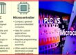
What is the difference between 8051 and microcontroller?
- These two are commonly used in different applications such as automobiles, medical instruments, embedded systems, etc. The basic difference is that the 8051 microcontroller comes with an 8-bit architecture, and the ARM microcontroller is a 32-bit architecture.
What is the difference between 8051 and MSP430?
- 8051 is 8 8-bit controller and MS430 is 16-bit microcontroller. 8051 micro-controller comes with 128 bytes of internal RAM
What are the functions of 8051?
- 8051 microcontroller is 40 pins dual inline package. These pins are used to perform different functions such as read, write, I/O operations, interrupts, and some others.
- It also has 4 ports and each port has 8 pins and used as input and output based on logic state of the pins.
Read also
That is a detailed post about 8051 microcontrollers if you have any queries ask in comments. Thanks for reading. have a good day.