PLCs Can Only Control What They Can Sense and Command
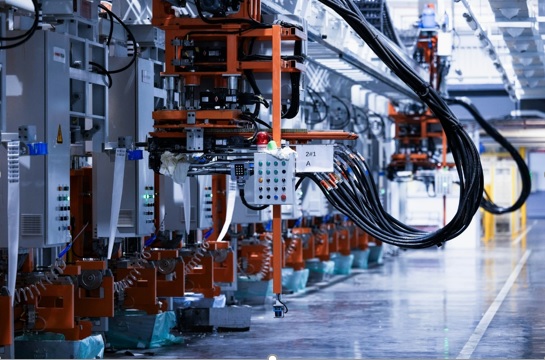
In industrial automation, a PLC is an important feature as the brain of the automated system. that runs scanning cycles, processes control algorithms, and applies ladder logic at microsecond speeds.
also a common capable processor completely separated from the physical factor floor without an intermediary bridge.
That main bridge is the Input/Output (I/O) system.
During the designing or defining of a control system, entry-level engineers and technical personnel commonly direct their focus toward processing speed, memory value, and CPU communication protocols.
Although processing power is important, real-world machine effectiveness and responsiveness are heavily affected by I/O architecture.
PLC does not work on conditions that are not properly detected and does not drive the actuator if the output phase is badly matched to the load.
Understanding of I/O modules working separately and transmitting signals is a basic need before getting a hardware or industrial control cabinet.
What Are PLC Input and Output Modules?
Input Modules
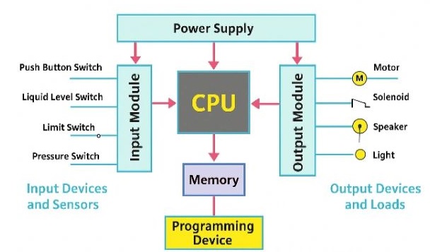
Input modules work as a sensory PLC system, getting a signal from physical field devices and transforming a high-voltage or varied field signal into a low-voltage logic signal, normally 5V DC, using a central processor.
Field sensors vary based on the project; binary devices like motion- and pressure-push buttons, mechanical limit switches, and photoelectric eyes offer simple state detection. Continuous calculation devices such as RTD temperature transmitters and piezoresistive pressure transmitters offer different voltage or current signals reflecting physical process variables.
These devices interface with two certain types of input modules:
Digital (Discrete) Inputs:
Get binary signals that show one of two different conditions, ON or OFF (TRUE or FALSE). Industrial standard digital inputs normally function on 24V DC or 120V AC, with the help of threshold detection circuitry to differentiate between active logic states and electrical noise.
Analog Inputs
Transform continuous physical quantities into digital numeric representations like 12-bit or 16-bit integer values through internal Analog-to-Digital Converters (ADCs).
Standard industrial analog signals come with 4–20 mA current loops, which offer high immunity to line voltage losses over long distances—and 0–10 V DC voltage signals.
Output Modules
When the CPU applies the logic program, output modules shift the low-voltage controller instruction into electrical signals having an energizing field devices.
These field devices are inductive loads, such as magnetic contactors and hydraulic solenoid valves, into visual indicator lamps, interposing relays, and speed-reference inputs for Variable Frequency Drives (VFDs).
Like output, output modules split into digital and analog variants:
Digital Outputs:
Switch power to discrete field loads, according to the switching component: mechanical relay, NPN/PNP transistor, or solid-state triac. These outputs convert field devices completely ON or OFF.
Analog Outputs:
using a digital-to-analog converter to output variable voltage or current signals. These drives divide the need for proportional control, like modulating control valves, VFD speed setpoints, or analog panel meters.
Matching electrical features, like load current, switching frequency, voltage losses, and inductive voltage spikes, between the output channel and field devices is important for controlling premature component failure.
Why the Right I/O Module Selection Has a Bigger Impact Than Many Realize
Defining input/output modules based only on channel counts is basic trapping when designing control systems. Longer-term functional working is based on signal quality, system diagnostics, and architectural scalability.
System Reliability Starts at the Interface
Industrial environments are caused by electrical noise. Larger electric motors, switching solenoids, and high-frequency inverter drives produce electromagnetic interference (EMI) and transient voltage spikes over conduit and cable trays.
High-quality input/output modules provide protection to sensitive microprocessors with galvanic isolations that get with internal optocouplers.
With transforming electrical signals into light and back to current, optocouplers block high-voltage surges and ground loops from affecting the PLC backplane. Coupled with hardware filtering to reduce contact chatter, accurate isolation ensures stable, jitter-free signal acquisition in bad industrial conditions.
Good Diagnostics Mean Less Downtime
Unplanned machine downtime affects generating yield. Standard input/output offer led status signs, with the latest diagnostic input/output modules giving granular visibility with individual channel level.
Advanced diagnostic modules have detection for field wire breaking, shorted output loads, channel power supply damage, and out-of-range analog signals.
By offering diagnostic bits directly into HMI alarm banners, technicians can detect damaged sensor wire or shorted solenoid coil in seconds, reducing hours of manual multimeter tracing.
Planning for Future Expansion
Manufacturing lines face frequent variations and upgradation capacity. Following a modular PLC design helps engineers to scale control. PLC design helps the system replace the central processing unit.
Inexperience of machine retrofits reversing of baseline about 15 to 20 percent spare channel capacity over local rack space and remote input/output bases reduces future engineering overhead.
When machine features need expansion, adding plug-in expansion modules reduces redesigning the main enclosure and control topology.
Digital vs. Analog I/O at a Glance
in short these primary I/O classifications make comparison during design evaluation; consider the core differences shown in the reference table below:
| Feature | Digital (Discrete) I/O | Analog I/O |
| Signal Type | Binary (ON / OFF) | Continuous range of values |
| Typical Devices | Push buttons, limit switches, proximity sensors | Pressure, temperature, flow, and level sensors |
| Example Signal Values | 0 or 1 (e.g., 0V DC / 24V DC) | 4–20 mA, 0–10 V DC, -10 to +10 V DC |
| Common Applications | Machine safety interlocking, sequence control | Closed-loop PID control, process monitoring |
Mostly practical, automated systems are not based on a single type. than they use hybrid methods; digital I/O handles high-speed acting machine safety measures, and sequencing I/O handles high-speed I/O continuously modul measures andl controls module measures, and fluid flow rates.
I/O Selection Errors New Engineers Make
Preventing oversights during hardware features saves important commissioning time and control field damages. Here are some main errors that Here are some key errors to avoid:
modules based only on channel quantity:
Use high-density 32-channel modules to save area, which causes wiring clutter or shared common wire damage when individual isolation is required.
Voltage and signal compatibility:
Mixing sourcing and sinking sensor techniques or misprinting AC vs. DC operating voltages for output loads
Forgetting future expansion needs:
Filling backplane space without leaving room or bus bandwidth for future expansion modules.
Overlooking environmental conditions:
If the module temperature rating is not fulfilled, conformal coating requirements for corrosive conditions and vibration tolerances for heavy machinery panels.
Digital outputs are interchangeable:
Use of relay outputs for high-frequency cycling resulting in mechanical contact wear, while transistor outputs provide high-speed PWM but not switch high-voltage AC circuits.
I/O Modules for Industrial Applications
To explain how the features are applied practically, let’s check how the I/O module needs to shift across distinct industrial parameters.
Small Packaging Machine:
Packaging: The instrument needs a high-speed sensor response for registering container movement and accurate trigger timing belts. These systems are based on high-density digital input/output,, having high-speed solid-state transistor switching and proper modular design for fitting in narrow machine frames.
Water Treatment System:
Water processing based on continuous physical variables. Different applications needing many analog inputs for flow rate, pH, and tank level monitoring, over outputs for position and direct relation of dosing valves
Due to treatment plants spanning larger areas, distributed remote input/output nodes connected through industrial Ethernet highly minimize long field-wiring runs back to the main control panel.
Factory Conveyor Line:
The cover system makes combinations of digital input to analog outputs for drive speed control. Due to the production line regularly adding diverting stations using expanding rack-based I/O, it ensures seamless future scalability.
Throughout this application process, engineers often review PLC I/O module features and pinout diagrams before finalizing their controller hardware selection, offering electrical support across all connected field instrumentation.
Conclusion
The central processor makes coordination of logic decisions, and the I/O system shows how effectively an automated system interacts with physical hardware. Evaluating I/O selection from a systemic features product’s high long-term advantages
Accurate electrical separation and noise filtering affect runtime stability. Integration channel finds easy troubleshooting and cuts operational downtime.
Proper allocation to extra capacity offers low-cost future expansion.
Mastering I/O architecture helps engineers to design robust, proper control systems that perform well under difficult factory conditions.