 Hello readers in this post we will discuss Impedance and Reactance Diagrams Of Electrical System There is a basic and easy way is used to drawn and explain the single line diagram in power system through use of impedance and reactance diagrams.
This way helps to study the power flow and complicated measurement of the system. As there is power calculation is somewhat difficult to process in the three-phase system and measurements are easy through the use of these diagrams for an unbalanced and unsymmetrical network.
For this complicated network, there is the usage of an impedance and reactance diagram to make the system simple and easy to understand. Here we learn different parameters that will help us to understand the power system easily and single line diagram.SO let’s get started
Impedance And Reactance Diagrams Of Electrical System
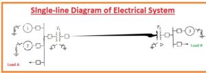
- For measurements of the operation of the system in case of the load is connected or there is a certain fault exists in the system is single line diagram is used for making the per phase system or single phase of the circuitry.
- There is resultant circuitry of the system shown in the above figure is created that is per the phase impedance diagram electrical power system
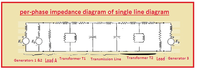
- If we do a load study of the system then lagging load denoted with A and B are shown through resistive and inductance reactance linked in series combination.
- At the impedance diagram, there is no display of limiting impedance denoted at the single line diagram linked among the neutral wire of the generator and ground terminal.
- It is due to that there is no current in-ground and neutral in the case of the balance system.
- SHunt current has no importance as compared to full load current so shunt admittance is not added in the circuitry.
- For fault calculation, there is no existence of resistance.
- resistance and inductive reactance are not added.
- Loads that do not include rotating devices like motors have less effect at the total line current in case of a fault so it is not added to the diagram.
- During fault measures, a synchronous motor is added because their output volts are working in case of short circuitry current.
- The diagram should consider the induction motor in consideration through generated volts in series to the inductive reactance it occurs in the case when it is used for calculation of current in when a fault exists in the system.
- There is no use of an induction motor in the circuit in case of current measures since after the occurrence of fault current delivering through the induction motor will be eliminated when it becomes a short circuit.
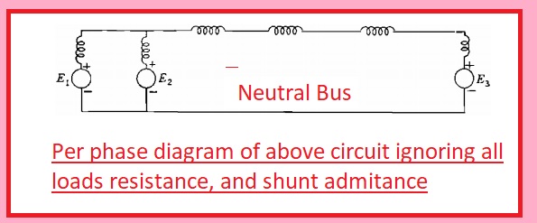
- If we want to make simple of our calculation for measurements of current by ignoring all static loads like a transformer, , shunt admittance, transmission line capacitance, and the resistance of the system then the impedance diagram will become per phase diagram shown below
Reactance diagram of power system
- The reactance diagram of a power system is a simple equivalent circuit of a power system that has many components of the power system with their reactances
- The reactance diagram can be made with the use of an impedance diagram of all resistive elements ignored
Impedance diagram of the power system
- The impedance diagram of the power system comes with an equivalent circuit of the power system where different components of the system are denoted with their simplified equivalent circuits. The impedance diagram works for load flow studies.
Read also:
- Difference Between Resistance and Impedance
- Three Windings Transformer Per unit Impedance
- Difference Between Resistance and Reactance
Faqs:
Can a reactance diagram be derived from an impedance diagram by?
- A reactance diagram can be made with the use of impedance if all resistive components are ignored. A reactance diagram is used for fault calculations.
What is the impedance diagram used for?
- The impedance diagram employed for load flow studies.
What is the difference between a single-line diagram and a reactance diagram?
A single-line diagram is a simple form of an electrical power system and a reactacne diagram simplified form of a reactance diagram. Different components like generators, transformers,s and loads are shown in a single-line diagram and the reactance diagram has the reactance of the main components connected in the system
What are the two basic types of electrical diagrams?
- wiring diagram and the schematic diagram
What is the difference between the two types of electrical diagrams?
- A schematic shows the function of electrical circuits and Wiring diagrams show wire connections and their location at the actual device,
What is the relationship between reactance and impedance?
- Reactance is the restriction force provided by the inductor and capacitor. Impedance is the summation of resistance and reactacne of AC circuits. Reactance can be inductive and capacitive
How is an impedance diagram drawn?
- In this diagram, resistance is at the base of the triangle reactance on the side and impedance at the hypotenuse
- In this AC circuit, the circuit impedance diagram formula: Z = R + ( X L − X C )2 where X L, X C are the inductor impedance (and the capacitor impedance
What are the two types of reactance in alternating current circuits?
- Reactance types are, inductive and capacitive
What is the difference between reactance and inductive reactance?
- If energy is released by reactance in the form of a magnetic field called inductive reactance and if energy is released in the form of electrical called capacitive reactance
What is the difference between reactance and resistance in an AC circuit?
- Resistance is a hindrance in current flow and reactance is a measurement of opposition in the value of change in the current