

 Hello, friends, I hope all of you are enjoying your life. In today’s tutorial, we will discuss What is Half Wave Rectifier. The diode is a device that used to transform ac current into dc current. The circuit used diodes to convert AC into DC is known as a rectifier. There are normally two types of halfwave rectifier and full-wave rectifier. In half-wave rectifier, a half cycle of ac waveform is transformed into direct current and in full-wave rectifier, both cycle or complete waveform of AC current is transformed into the direct current.
In today’s post, we will have a detailed look at half-wave rectifier its circuit, applications, and some other related parameters. There are mostly electronic devices that operate on DC as our power system is AC. So these rectifier circuits help us to operate these devices. So let’s get started with the Half Wave Rectifier.
What is Half Wave Rectifier?
- The rectification is a process that used to transform AC signal into DC and the circuit used to transform AC into DC is known as a rectifier.
- Almost every electronic device that operates on dc power supply and input source of dc supply is ac uses rectifier circuits to transform ac into dc.
- For a practical understanding of half-wave rectifier, first of all, we discuss the operation DC supply.
Basic DC Power Supply
- All active devices such as a transistor, TRIACs, etc operate on direct current, and direct current they needed dc power supply or battery.
- The input of dc supply is ac one twenty standard volts that convert into the direct current.
- Now a day in electronic engineering and circuits the circuitry of dc power supply is very common to us so its knowledge is compulsory for the understanding of other circuits.
- The devices that operate at dc current are TVs, computers, DVD players, etc. The output voltage of a dc supply depends on the devices for which it is designed normally voltage power supplies are designed.
- In the given figure the block diagram if the dc power supply is shown.
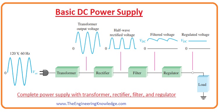
- In the figure, you can see different parts of dc power supply in the first part input AC supply is provided to the transformer that steps down at the required level.
- In some cases, a step-up transformer is used to increase the voltage level
- The output of the transformer goes to the rectifier circuit that converts it into the dc voltage. it is shown in below figure.
- After that dc output of the rectifier goes to a filter circuit that removes the fluctuation and makes pure dc output.
- With the filter circuit regulator circuit is connected that maintains the required voltage level and then the specified voltage goes to the load.
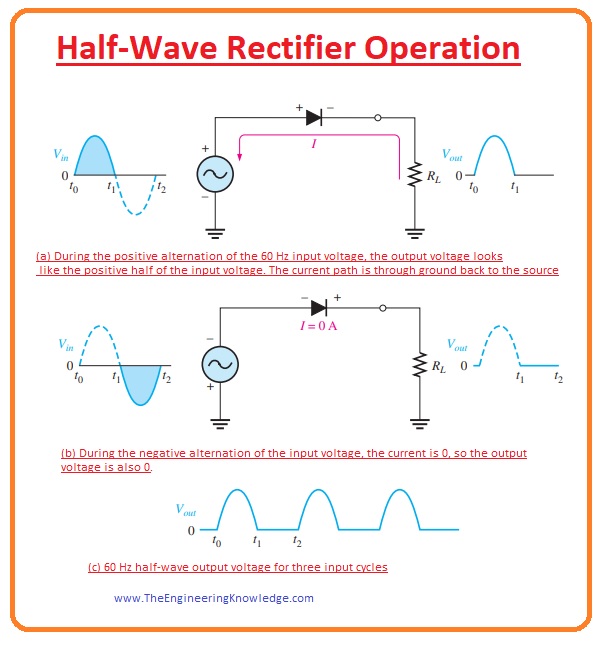
Half-Wave Rectifier Operation
- In the given figure the circuit of a half-wave rectifier is shown. In this circuit, an input ac supply is provided to the diode and resistance as load is attached in series with the diode.
- For the understanding of half-wave rectification, we discuss both half of ac signal one by one.
- When the first half of AC wave passes through the diode it operates as forward biased and this part of the signal is rectified into the dc. This process is denoted (a) figure.
- When the negative half of the diode passes through the diode it now in reversed biased condition and no current passes through the diode. This process is denoted as (b) in the above figure.
- In figure denoted as (c) the output of the halfwave rectifier is shown.
Average Value of the Half-Wave Output Voltage
- The value of voltage measured by the voltmeter is known as the average value of the half-wave
rectified output voltage. - It can also determine by calculating the area of the curve obtained after the rectification process as it is shown in a given figure.
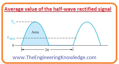
- After finding area divide it by the numbers of radians in the output rectified complete cycle.
- The average value of voltage is shown in the below equation.
- From this equation, you can see that the VAVG is almost 31.8 percent of VP of the half-wave rectified voltage.
VAVG =Vp/Π
Barrier Potential Effect on Half-Wave Rectifier Output
- During the positive half of the ac wave, 0.7 volts are used to cross the potential barrier of a diode.
- So, as a result, the half-wave peal output is equal to 0.7 less than the peak value of input as shown in a given figure. 2–23
- The equation for peak output voltage is mentioned here.
Vp(out) =Vp(in) -0.7 V——–(a)
- In an ideal diode, the potential barrier is not considered so we get the output without 0.7V loss.
- While in case of a practical diode potential barrier effect can not be neglected.
Peak Inverse Voltage (PIV)
- The value of peak inverse voltage is similar to the peak value of an input voltage and the diode should have the ability to bear this repetitive reverse voltage.
- In the given figure, you can see that, the extreme value of reverse voltage denoted as (PIV) exits at the peak of every negative repetition of the input voltage when the diode is in reverse bias condition.
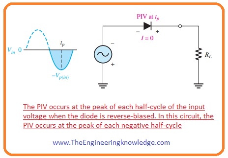
- The rating of diode should be twenty percent greater than the PIV value.
PIV= Vp(in)—(b)
Half Wave Rectifier Transformer Coupling
- In the given figure, you can see the transfer coupled with the rectifier circuit. There are 2 advantages of a transformer with a rectifier circuit.
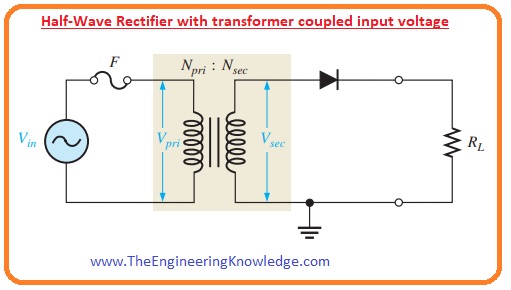
- First is that we can vary the value of voltage according to circuit requirements and the second is that the transformer provides protection to the rectifier circuit from the input source.
- The value of the voltage step down by the transformer can calculate from the turn ratio of the transformer.
- Turn ratio is the ratio between the number of turns of secondary windings to the number of turns of the primary winding.
- The transformer having a turn ratio less than one is called a step-down and a transformer having a turn ratio greater than one is called a step-up.
- The relation between turn ratio and voltage value at the transformer windings is shown below.
Vsec = nVpri
- If the value of n (turn ratio) is larger than one then the value of the secondary voltage is larger than the primary voltage.
- If n is less than one than the secondary voltage is less than the primary voltage.
- If the ratio is equal to one than the voltage at primary and secondary winding will be equal.
- The value of peak secondary voltage Vp(sec) in a rectifier circuit having a transformer is equal to the equation denoted as a.
- So this equation can be written as.
Vp(out) = Vp(sec) – 0.7 V
- The equation (b) can also be written as.
PIV= Vp(sec)
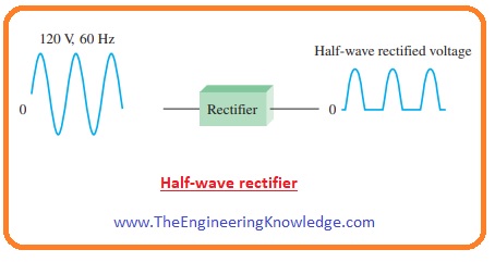
Half Wave Rectifier Circuit
- A half-wave rectifier circuit transforms an alternating current (AC) signal to a pulsing direct current (DC) signal. It does this by allowing current to flow in just one direction through a single diode, essentially “chopping off” one-half of the alternating current signal.
The input alternating current signal is applied to the circuit’s input terminal, which is commonly linked to a transformer to step down the voltage. The transformer’s output is given to the anode of diodes and the cathode is connected to a load resistor - When the alternating current signal is positive, the diode conducts, and current flows through the load resistor. When the alternating current signal is negative, the diode does not conduct and there is no current flowing through the load resistor.
As a result, the output voltage of circuits is a series of positive pulses which are related to positive half cycles of input ac signal.. To decrease ripple and give a more steady DC voltage, the output voltage is often smoothed with a capacitor. - While a half-wave rectifier is simply structured and less costly for ac to dc conversion and has some limitations. It has a lower output voltage and current than a full wave rectifier since it only uses half of the input signal. Furthermore, the output voltage is not constant and varies with load resistance and input voltage
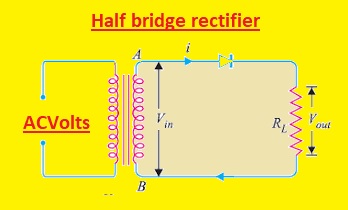
Half Bridge Rectifier
An electrical circuit known as a half bridge rectifier transforms alternating current (AC) signals into pulsed direct current (DC) signals. In contrast to a full wave rectifier, it only uses two diodes.
The input terminal of the circuit, which is normally coupled to a transformer to step down the voltage, receives the input AC signal. The center tap of a transformer, which is coupled with two diodes and a load resistor, is where the output of the transformer is next linked.
The diode attached to the upper end of the Centre tap conducts during the positive half-cycle of the AC signal, allowing current to pass through the load resistor. The diode attached to the lower end of the centre tap conducts during the negative half-cycle, allowing current to pass through the load resistor in the opposite direction.
A succession of positive and negative pulses that correspond to the positive and negative half-cycles of the input AC signal make up the circuit’s output voltage as a result. A capacitor is usually used to smooth out the output voltage in order to lessen ripple and produce a more reliable DC voltage.
The output voltage and current are higher and the circuit design is easier for a half-bridge rectifier compared to a full-wave rectifier. It has certain drawbacks, though, including a larger peak inverted voltage between the diodes and a higher ripple voltage because only two diodes are used.
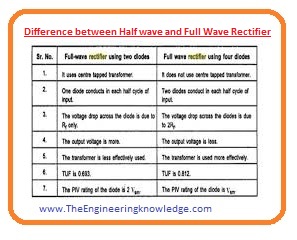
Difference Between Half Wave and Full Wave Rectifier
- These are some differences between half-wave and full-wave rectifier.
|
Half Wave Rectifier |
Full Wave Rectifier |
| In half-wave rectification positive half of input, ac wave is converted into dc. | In full-wave rectifier complete ac waveform is converted into the dc current. |
| The rectification efficiency of a half-wave rectifier is 40.6 percent. | Its efficiency is 81.2 percent. |
| Its ripple factor is 1.21. | Its ripple factor is 0.482. |
| 0.286 is the transformer utilization factor of a half-wave rectifier. | Its transformer utilization factor is 0.692 |
| It provides voltage regulation of good quality. | Its voltage regulation is better than the half-wave rectifier. |
| Its ripple fundamental frequency is equal to the input supply frequency. | Its ripple frequency is double the input supply frequency. |
| Its form factor is 1.57 | Its form factor is 1.11 |
| Its peak factor is two. | Its peak factor is 1.414 |
| Its circuit uses only a single diode. | Its circuit has two to four diodes. |
Half Bridge vs Full Bridge Rectifier
| Feature | Half Bridge Rectifier | Full Bridge Rectifier |
|---|---|---|
| Number of diodes | 2 | 4 |
| Voltage rating of diodes | Higher | Lower |
| Output voltage | Half of input voltage | Full input voltage |
| Output current | Lower than full bridge | Higher than half bridge |
| Efficiency | Lower | Higher |
| Circuit complexity | Simpler | More complex |
| Peak inverse voltage | Higher | Lower |
| Ripple voltage | Higher | Lower |
| Transformer utilization | Half | Full |
| Cost | Lower | Higher |
| Size and weight of the circuit | Smaller and lighter | Larger and heavier |
| Applications | Low-power applications such as mobile chargers, small inverters | High-power applications such as industrial power supplies, motor drives |
FAQs:
How Does a Half-Wave Rectifier Work?
- A half-wave rectifier is an electrical circuit that converts ac signal to dc signal by allowing one-half of the wave to flow. The load resistor, the AC source, and a single diode are all linked in series in the circuit. The diode conducts and permits current to pass through the load resistor during the positive half cycle of the AC waveform, producing a positive half cycle of the output waveform. The diode is reverse-biased and does not conduct during the negative half cycle of the AC waveform, producing no output. As a result, the output waveform is composed of numerous happy half cycles.
Where is a Halfwave Rectifier Used?
- When the DC voltage is not crucial, such as in low-power applications, battery chargers, and small signal detection circuits, a half-wave rectifier is frequently used.
What is Half Wave Rectifier Working Principle?
- A half-wave rectifier’s operation is based on a diode’s ability to allow current to flow only in one direction. The diode conducts and permits the current to pass through the load resistor during the positive half cycle of an AC waveform, producing a positive half cycle of the output waveform. The diode is reverse-biased and does not conduct during the negative half cycle of the AC waveform, producing no output. As a result, the output waveform is composed of numerous happy half cycles.
What are Half-Wave and Full-Wave Rectifiers?
- The diodes used in the circuit tells about that how half-wave and full-wave rectifier are different. A full-wave rectifier uses two or 4 diodes for conversion of the complete ac signal to dc, as opposed to a half-wave rectifier that only transforms one-half of the AC signal. As a result, the half-wave rectifier, a full-wave rectifier produces a smooth dc signal having less ripple.
Why Half Wave Rectifier is Used?
- In low-power applications, battery chargers, and small signal-detecting circuits where the DC voltage is not crucial, a half-wave rectifier is utilized. It is a straightforward circuit that costs little money, is simple to build, and only needs one diode. Its efficiency is inferior, though, and the DC output voltage it generates is just half the AC input voltage.
So friends that is the detailed post on the half-wave rectifier I have each and every parameter related to the half-wave rectifier. If you have any queries about this post ask in comments. Thanks for reading. See you in the tutorial.
Read Our Latest Post: