 Hello, readers welcome to the new post. Today we will discuss Fading LED Light Circuit. Currently, the practical applications of LEDs are increasing day by day since their prices are low and operate for long time intervals. Its common applications are in vehicles, decoration lights, lamps, and different circuits.
There are some uses of LED that it used in circuits that enhance or reduce the light intensity according to the number of people coming and leaving a particular area. This operation of LEDs is called LED fading.
Vorlane Led lights are gaining popularity because one can use these while commuting, constructing or even getting the stage ready for some performance. It is important to understand the mechanism of these lights to understand them better.
Fading LED Lights Circuit Working Principle
- The circuit of this LED application consists of a transistor and capacitor. The diode used in this circuit operates in the forward-biased state. The light emitted by the LED when its positive terminal is attached to the positive terminal of the battery and the negative pin of the LED with the negative of the battery.
- This circuit can be configured if the negative pin is ground connected and at the positive pin, volts are provided.
- If we press the button of the circuit capacitor gets started charging and discharging that results in LED to start fading.
Introduction to BC547
- BC547 transistor is used in our project. It has a gain value from 110 to 800 that defines its amplifier operation.
- The highest quantity of current which can flow about a collector of this transistor is about 100mA, so try to avoid less load about this component.
- For biasing this transistor 5milliampers current can be provided at the base pin.
- In case of complete biased operation, there is one hundred milliampere current that can flow across the CE junction. This stage of the transistor is called saturation region and normally volts about VCE or VBE is two hundred to nine hundred millivolts
- If Ib is not provided transistor is in off state known as cut off region and the value of the base-emitter is about 660mv
How to buy BC547?
- You can by using the below link
buy BC547
Component of Project
- The component used in this circuit are listed below.
- Capacitor
- BC547 Transistor
- LED
- Battery
- 555 Timer IC
- When volts are provided through the use of a battery that s nine volts the IC 555 timer provides initiates the oscillation of a square signal based on a timing resistor and capacitor. In this circuit, there is the connection of the capacitor with the IC and it gets charged through the IC. At the start timer has high output, therefore, the transistor gets on and LED emits light, during this process capacitor gets charged and the timer output gets low and the transistor get a saturation point and the capacitor gets started to discharge through the transistor Q1. This charge goes to LEDs that glow with high intensity. This process will last till the power supply is attached
- PCB from PCBWAY: PCBWAY is an electronic-based company that provides different solutions for electronic projects and PCB services. The main benefit you will get through PCBWay PCB manufacturing service is that you can get a single solution for PCB manufacturing and assembly with great quality features. By getting your first prototype board from PCBWAY get the low volume manufacturing and easy scaling for your project. PCBWAY is an older and expert PCB creator and SMT services provider in China.
- They are experts in all services like customer services PCB manufacturing PCBA with proper research and developments. PCB construction is considered not an easy process for newer but PCBWAY has eliminated all problems for that person since they are leading with an expert team of engineers.
- Through the use of PCBWAY online services, you can get easy orders for PCB construction and project assembly and you will have all updates about your products regularly.
- When PCB manufacturing is completed will be sent to your at your given address and in the given time interval

At PCBWay, all boards pass the most rigorous tests in addition to basic visual inspection. They accept most of the testing and inspection equipment used in the industry, such as Flying Probe Testers, X-Ray Inspection Machines, and Automated Optical Inspection (AOI) Machines. Every day they have 50+ new engineers around the world using their PCBs for their work who trust them for their reliable quality. Quality control
Fading LED Light Circuit Working
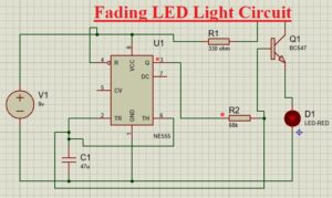
- LED fading circuit is very easy to construct in this project 555 times IC is used in Astable mode and transistor used for current amplification.
- In Astable mode 555 timer work at a certain level of frequency that has a high and low signal at pin 3.
- So if we have a high signal at pin 3 transistors get started as amplifiers and do the current amplification.
- This current is used by the capacitor and gets charged up to 2/3Vcc at the LED glows.
- After that, if pin 3 has a low signal transistors get off and capacitors get discharged through CE junction.
- Capacitor discharges in the LED result in a fading effect.
- When the capacitor discharges are completed LED glow decreases. After that again pin 3 is high and the capacitor again gets charged and the led glows.
- The LED fading relies on the resistance and capacitor used in the circuit. If you have a high-value capacitor LED get fades slowly
Application of LED Fading
- These circuits are used in markets and malls to decrease the lighting when not more people are there
- These circuits are used for security purposes
- It is used in home and business
- It used as an indicators
Circuit Limitations
- The LED gets the required volts for operation if not can affect its operation
- The color of LED can be varied due to temperature and time duration
Read also
- Fading LED Light Circuit-Proteus
- Water Level Indicator Circuit-Proteus
- Dual Power Supply Circuit-Proteus Simulation
- Basic LED Flasher Circuit using 2N3094-Proteus
- DC Motor Control in Proteus using IC L293D
That is all about the Fading LED Light Circuit all details has explained if you have any questions ask here.