 Hello, friends welcome to the new post. In this post, we will have a detailed look at the Equivalent Circuit Of A Transformer. The transformer is an electrical instrument that is used to vary the level of voltage given at the input and shown at the output according to the configuration used either step up or step down.
Here we discuss its circuit configuration to see the practical working of the transformer and its related parameters. So let’s get started with the Equivalent Circuit Of A Transformer
Equivalent Circuit Of A Transformer
- The losses which exist in the practical transformer should be discussed to see the practical understanding of transformer circuitry.
- The main factors that should be considered are mentioned here.
- Copper losses are caused due to the losses across the primary and secondary windings of the transformer. They are proportionate to the square of current passing in the coils at the primary and secondary sides.
- Eddy’s current losses exist in the core of the transformer. Are proportionate in relation to the square of voltage given at the transformer.
- The third factor is hysteresis loss is related to the configuration of magnetic domains in the core through half part of signal.
- Leakage flux is the fourth factor that moves ours from the core and windings. Due to this flux self-inductance is generated in the primary and secondary windings and in the circuitry this inductance is considered.
Exact Equivalent Circuit of a Real Transformer
- It is certain to make equivalent circuitry which is considered in all main parameters of the transformer.
- Every inadequacy of the model is take into consideration and their outcomes are added in the transformer structure.
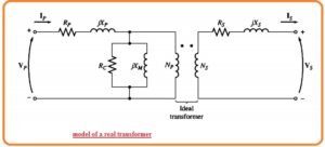
- The simplest factor in the circuitry is copper losses that are resistance losses in both windings or transformer
- To design this loss resistance Rp is in the primary circuitry of the transformer is posited and resistance Rs at secondary circuitry.
- Due to leakage flux at primary windings voltage is induced.

- as the most part of the leakage flux is passing through the air and as the reluctance air is constant and has large value than the reluctance of core the flux has a direct relation to the primary circuitry current Ip and flux of sedentary is in direct relation to the secondary current.
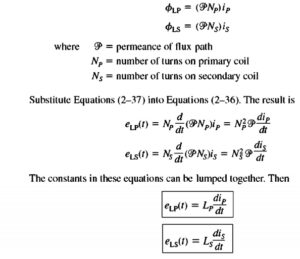
- in the above equation, Lp is self-inductance of the primary side and Ls is the self-inductance of the secondary side. So the leakage flux now created through primary and secondary winding inductances.
- How to construct core excitation factor:
- The magnetization current Im is current that is proportionate to the voltage given to the core and lags the given voltage through ninety degrees therefore it can be constructed through the reactance XM linked about the primary voltage supply.
- The core losses current Ih+e is current proportionate to the voltage given to the core which is in phase to the voltage given therefore it can be constructed through resistance Rc linked to the primary voltage supply.
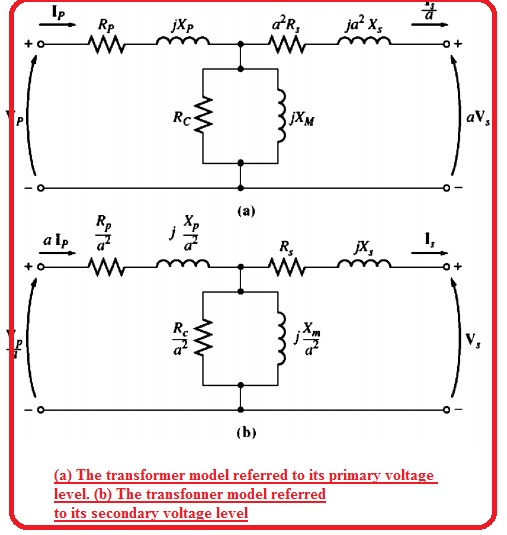
- The resultant equivalent circuitry of the transformer can seen here.
- Note that components creating the excitation branch are posited in the primary resistance Rp and primary inductance Lp.
- It is due to the voltage given to the core is equal to the input voltage less than the inner voltage losses at the windings.
- Though circuitry in the above figure is the correct circuit of the transformer it is not good to use.
- For practical understanding, the circuitry comprises a transformer that is generally compulsory to transform the complete circuitry in equivalent circuitry having one voltage level
- So equivalent circuitry should be referred to the primary side or secondary side in a solution of mathematical problems.
- The below diagram equivalent circuitry of transformer referred to the primary side and in figure shown denoted as b the equivalent circuitry referred to the secondary side.
How to Get Free Coupons for your new Project
- Hu readers till now i hope you have well aware of the transformer and circuit of the transformer. But now i am going to explain something interesting for you.
- As you are an electrical or electrical engineer or students of these engineering or new to this field are going such project where you are using a transformer and different electronic components for project making.
- As you are new to the engineering field you must search such source that can provide sources for your project and different sponsor program that help to create your work
- I am going to resolve your problem for that purpose here I am introducing such sponsors that offer coupons for your work.
- Use of coupons is a good method to use less amount for getting something but getting such an opportunity is not an easy task.
- Here I am introducing such a service that offers coupons to create your projects at reasonable prices and in some cases your complete work can be done free of cost.
- these coupons are very fruitful in the case when we are creating different projects at a large scale and where high cost is needed to complete work
- PCBWAY is china based manufacturer that offers services related to PCB, PCB prototype and SMD stencil, and other related with affordable prices
- They offering a platform for new engineers students, innovators educators to create their different projects through PCB boards and other electronic devices in a handsome package
How to get Coupons from PCBWAY
- Here main methods are described to get free coupons from PCBWAY to make your new projects.
- This program of this PCB supplier is for students, teachers, and anyone who is going to create the project.
- Through this program, we can get a ten to fifteen percent discount and also has the opportunity to get hundred dollar coupons that offer five times a month..
- The other method is the referral program of PCBWAY is employed in different places to permits customers to get free amounts or coupons through sending invitations to others.
- Through his offer gift cash and coupons for newbie and already registered users. Just you has to invite your friends and other users through a referral link.
- For one new member you can get a twenty percent discount coupon with that can earn ten percent price back that used for ist order,
Approximate Equivalent Circuits of Transformer
- The transformer circuitry shown above is complicated to obtain accurate results in different applications.
- The main issue is that the excitation branch of the circuitry is added to another node of circuitry that is under study
- The excitation branch is like a small current than the load current of the transformer.
- In real it is less than in normal situations it results totally ignored voltage losses Rp and Xp.
- Since it is accurate the basic circuitry can be generated that functioned like normal circuitry.
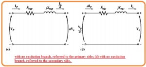
- The excitation brach is just moving to the front side of the transformer and primary and secondary impedances are in series combination.
- This impedance are added making the circuitry of the transformer as shown below.
- In certain applications, the excitation brach can be ignored completely without giving serious results
- In this condition the equivalent circuitry of the transformer now becomes
How to Determine Values of Components Transformer Circuit
- It is certain to finds the values of inductance and resistance in the circuitry of the transformer.
- The adequate simplification of these parameters can get through 2 tests open circuit and short circuit test.
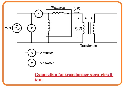
- In the open circuitry test transformer secondary side is open and the primary is linked to the full rated voltage.
- See the circuit in the below figure.

- In these conditions, the input current should be passing in the excitation branch of the transformer.
- The series components Rp and Xp are very less than the Rc and Xm to effect sufficient voltage loss therefore all input voltage is lost about the excitation branch.
- The open circuitry test points can sen her.
- Full rated voltage is given to the primary side of the transformer and input voltage input current and input power at the transform are find.
- Through this data, it is certain to finds the P.F of input current and so both magnitude and angle of excitation impedance.
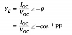
- The simple method to find the parameters of Rc and Cm is to see the ist to the admittance of the excitation branch.
- The conductance of core losses is mentored here,

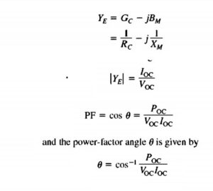
- The P.f is lag in the case of real transformer therefore the angle of current lags the angle of voltage by some angle.
- The admittance is given here
Short Circuit Test
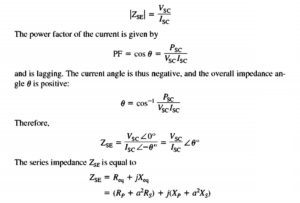
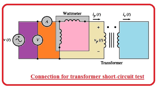
- In this test secondary points of the transformer are short-circuited and primary points are linked to the less voltage supply.
- The input voltage is set to the current is short-circuited and windings is similar to the rated value.
- 1he input voltage, current, and power are again found
