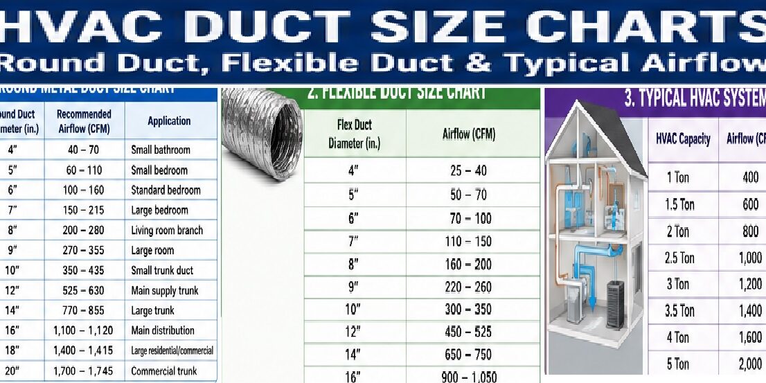
An HVAC duct sizing chart is helpful for installation, EPCs, and engineers to get details of an airflow system that is calculated in cubic feet per minute (CFM). Main features provide friction losses at a rate of 0.1 inches of water column per 100 feet of duct and provide high-efficiency HVAC operation with noiseless features.
The use of proper duct size for design purposes is important since a small error increases system cost. In this post, we will cover details about the duct size chart and relevant features.
Basic Duct Sizing Principles
Before obtaining details about the duct size chart, it is important to first understand the main requirements for installation. Proper duct design basically balances functions between airflow volume, friction losses, and air velocity. If the value of any component varies, it can affect the performance of others.
Airflow Volume
Airflow volume is calculated in cubic feet per minute (CFM), which is the conditioned air volume needed for heating or space cooling to operate properly. That volume is defined with formal load values, according to ACCA Manual J analysis, which follows room dimensions, insulation, occupancy, and climate window details. Faulty CFM values result in incorrectly sized systems; this issue arises when we refer to a chart.
Air Velocity
This factor is calculated in feet per minute, which is the speed at which air moves in ductwork. Those are important engineering factors: slow air and distance not reaching registers, a result of faulty distribution; and high speed, a result of noise and high static pressure, affecting blower motor functioning.
Friction Loss
Friction losses, loss of pressure, and losses of air forces when flowing through ducts, and also in fittings. Its measuring unit is inches of water column per 100 feet.
Net system friction based on all components like transitions, elbows, takeoffs, and dampers. Some size chart standards are 0.1 inches, which is best for the system. complicated system having long runs, different fittings, or flex duct needed old 0.08″ values
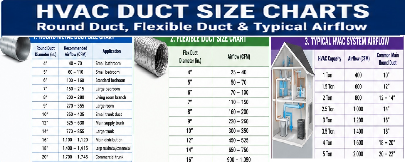
HVAC Duct Size Chart (Round Metal Duct)
| Round Duct Diameter (in.) | Recommended Airflow (CFM) | Application |
| 4″ | 40–70 | Small bathroom |
| 5″ | 60–110 | Small bedroom |
| 6″ | 100–160 | Standard bedroom |
| 7″ | 150–215 | Large bedroom |
| 8″ | 200–280 | Living room branch |
| 9″ | 270–355 | Large room |
| 10″ | 350–435 | Small trunk duct |
| 12″ | 525–630 | Main supply trunk |
| 14″ | 770–855 | Large trunk |
| 16″ | 1,100–1,120 | Main distribution |
| 18″ | 1,400–1,415 | Large residential/commercial |
| 20″ | 1,700–1,745 | Commercial trunk |
Flexible Duct Size Chart
| Flex Duct Diameter (in.) | Airflow (CFM) |
| 4″ | 25–40 |
| 5″ | 50–70 |
| 6″ | 70–100 |
| 7″ | 110–150 |
| 8″ | 160–200 |
| 9″ | 220–260 |
| 10″ | 300–350 |
| 12″ | 450–525 |
| 14″ | 650–750 |
| 16″ | 900–1,050 |
Typical HVAC System Airflow
| HVAC Capacity | Airflow (CFM) | Common Main Round Duct |
| 1 Ton | 400 | 10″ |
| 1.5 Ton | 600 | 12″ |
| 2 Ton | 800 | 12–14″ |
| 2.5 Ton | 1,000 | 14″ |
| 3 Ton | $1,200.00 | 16″ |
| 3.5 Ton | $1,400 | 18″ |
| 4 Ton | $1,600 | 18–20″ |
| 5 Ton | $2,000 | 20–22″ |
Professional HVAC Duct Size Chart (Round & Rectangular Duct)
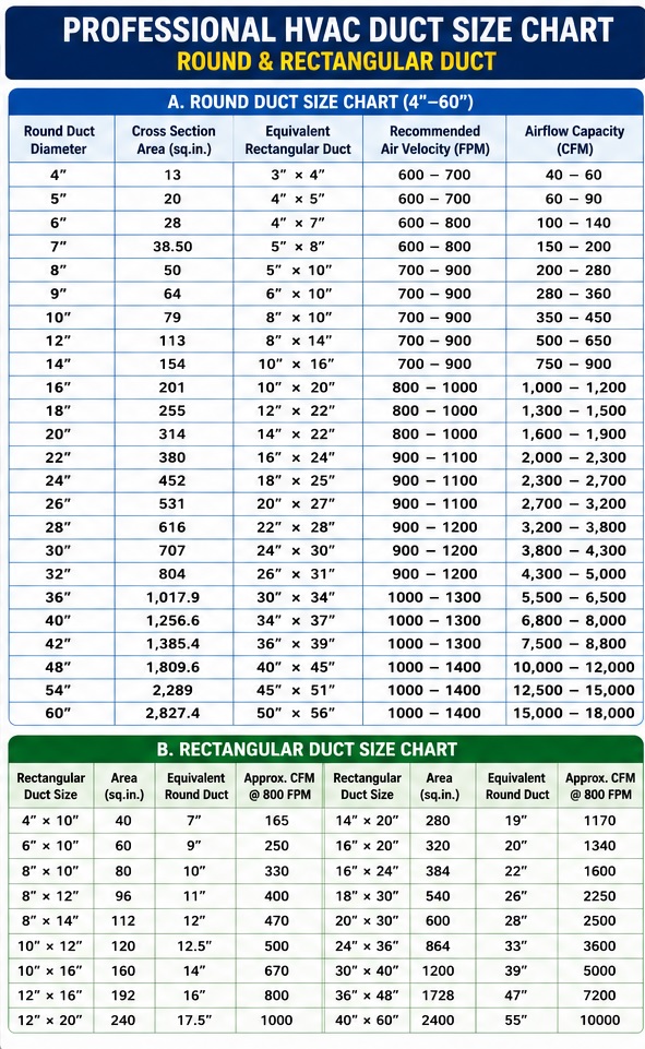
Round Duct Size Chart (4″–60″)
| Round Duct Diameter | Cross Section Area (sq.in.) | Equivalent Rectangular Duct | Recommended Air Velocity (FPM) | Airflow Capacity (CFM) |
| 4″ | 13 | 3″ × 4″ | 600–700 | 40–60 |
| 5″ | 20 | 4″ × 5″ | 600–700 | 60–90 |
| 6″ | 28 | 4″ × 7″ | 600–800 | 100–140 |
| 7″ | 38.50 | 5″ × 8″ | 600–800 | 150–200 |
| 8″ | $50 | 5″ × 10″ | 700–900 | 200–280 |
| 9″ | 64 | 6″ × 10″ | 700–900 | 280–360 |
| 10″ | 79 | 8″ × 10″ | 700–900 | 350–450 |
| 12″ | 113 | 8″ × 14″ | 700–900 | 500–650 |
| 14″ | 154 | 10″ × 16″ | 700–900 | 750–900 |
| 16″ | 201 | 10″ × 20″ | 800–1000 | 1,000–1,200 |
| 18″ | 255 | 12″ × 22″ | 800–1000 | 1,300–1,500 |
| 20″ | 314 | 14″ × 22″ | 800–1000 | 1,600–1,900 |
| 22″ | 380 | 16″ × 24″ | 900–1100 | 2,000–2,300 |
| 24″ | 452 | 18″ × 25″ | 900–1100 | 2,300–2,700 |
| 26″ | 531 | 20″ × 27″ | 900–1100 | 2,700–3,200 |
| 28″ | 616 | 22″ × 28″ | 900–1200 | 3,200–3,800 |
| 30″ | 707 | 24″ × 30″ | 900–1200 | 3,800–4,300 |
| 32″ | 804 | 26″ × 31″ | 900–1200 | 4,300–5,000 |
| 36″ | 1017.9 | 30″ × 34″ | 1000–1300 | 5,500–6,500 |
| 40″ | 1256.6 | 34″ × 37″ | 1000–1300 | 6,800–8,000 |
| 42″ | 1385.4 | 36″ × 39″ | 1000–1300 | 7,500–8,800 |
| 48″ | 1809.6 | 40″ × 45″ | 1000–1400 | 10,000–12,000 |
| 54″ | 2289 | 45″ × 51″ | 1000–1400 | 12,500–15,000 |
| 60″ | 2827.4 | 50″ × 56″ | 1000–1400 | 15,000–18,000 |
Rectangular Duct Size Chart
| Rectangular Duct Size | Area (sq.in.) | Equivalent Round Duct | Approx. CFM @ 800 FPM |
|---|---|---|---|
| 4″ × 10″ | 40 | 7″ | 165 |
| 6″ × 10″ | 60 | 9″ | 250 |
| 8″ × 10″ | 80 | 10″ | 330 |
| 8″ × 12″ | 96 | 11″ | 400 |
| 8″ × 14″ | 112 | 12″ | 470 |
| 10″ × 12″ | 120 | 12.5″ | 500 |
| 10″ × 16″ | 160 | 14″ | 670 |
| 12″ × 16″ | 192 | 16″ | 800 |
| 12″ × 20″ | 240 | 17.5″ | 1000 |
| 14″ × 20″ | 280 | 19″ | 1170 |
| 16″ × 20″ | 320 | 20″ | 1340 |
| 16″ × 24″ | 384 | 22″ | 1600 |
| 18″ × 30″ | 540 | 26″ | 2250 |
| 20″ × 30″ | 600 | 28″ | 2500 |
| 24″ × 36″ | 864 | 33″ | 3600 |
| 30″ × 40″ | 1200 | 39″ | 5000 |
| 36″ × 48″ | 1728 | 47″ | 7200 |
| 40″ × 60″ | 2400 | 55″ | 10000 |
Duct Velocity Selection factor
| Duct Application | Recommended Velocity |
| Residential Supply Branch | 500–700 FPM |
| Residential Main Supply | 700–900 FPM |
| Commercial Supply Duct | 900–1500 FPM |
| Return Air Duct | 400–700 FPM |
| Fresh Air Intake | 500–800 FPM |
| Exhaust Duct | 800–1500 FPM |
| Industrial HVAC | 1200–2000 FPM |
Friction Loss Reference Chart
galvanized steel duct friction loss
| Duct Type | Normal Friction Rate |
| Residential HVAC | 0.05–0.08 in. w.g./100 ft |
| Commercial HVAC | 0.08–0.15 in. w.g./100 ft |
| Industrial Systems | 0.15–0.30 in. w.g./100 ft |
| Duct Diameter | Approx. Friction Loss @ Normal Airflow |
| 6″ | 0.10–0.25 in. w.g./100 ft |
| 8″ | 0.08–0.18 in. w.g./100 ft |
| 10″ | 0.06–0.15 in. w.g./100 ft |
| 12″ | 0.05–0.12 in. w.g./100 ft |
| 16″ | 0.04–0.10 in. w.g./100 ft |
| 20″ | 0.03–0.08 in. w.g./100 ft |
| 24″ | 0.02–0.06 in. w.g./100 ft |
| 36″+ | 0.01–0.04 in. w.g./100 ft |
How to Use the Duct Sizing Chart
Conversion of engineering requirements into a working HVAC system required accuracy. These points are used for the following required duct run sizing in real working conditions.
CFM calculation
Before getting to the chart, find the CFM value for all rooms with professional analysis. Do not apply the 1 cfm per square foot shortcut for final parameters that do not consider ceiling height, glazing, insulation, and environmental conditions.
50 to 75 cfm is used for small rooms, and larger living areas need 300 cfm or higher.
Friction Loss Rate
Use accurate friction loss rates before duct sizing. In normal residential and light systems use of rigid metal ductwork, 0.1 inches per 100 feet is the baseline. For complicated designs having different fittings, 0.08″ is used
Chart reading
After CFM and friction rate are in hand, find CFM through the sizing chart in the red row for the selected friction rate column and get duct dimensions.
Avoid mistakes in duct sizing.
Proper charts work well when we use them properly. So avoid these errors to get good results.
Not considering Fittings and Bends
Duct size based on linear feet without considering resistance fittings causes a high-cost design, which is a common error. Equivalent length added to run with elbow, transition, damper, and tee. One sharp 90-degree elbow results in adding up to 30 feet of equivalent straight duct.
If not considering these factors, real static pressure across measured values causes chronic issues when air moves to distant registers.
Return air duct undersizing
For duct sizing, not considering return is also a costly HVAC error. An undersized return affects the air handler, causes high energy usage, strains the blower motor, and also causes a frozen evaporator coil in cooling mode or causes overheating of the heat exchanger in heating mode.
Return duct size should follow net CFM demand for accurate velocity, like 500 to 700 FPM for residential.
Flex duct and rigid duct are used as replacements.
With the help of a rigid metal sizing chart and installing flexible duct with the same dimensions it causes damage. That flex duct causes high turbulence and friction resistance. For providing the same CFM, like rigid duct design, we needed to increase the flex duct size by about one to two inches in diameter.
Single Chart for All Duct Types
Ducts made with different materials, such as galvanized steel, fiberglass duct board, aluminum, spiral round, and flexible design come with different interior surfaces, structures, and values that affect friction losses.
So, follow the proper engineering data for the specific product installation.
What is the basic rule for duct sizing?
For designing an HVAC system, the main rule for duct sizing is to follow basic details that are helpful for finding accurate dimensions for air ducts to offer the required airflow in the space.
These details offer a fast way for getting idea of fast duct sizes according to different parameters such as airflow rate and duct shape.
Practical example
Let’s assume the HVAC system is made for providing 600 cfm of conditioned air at your office. Based on a standard duct sizing chart, a 12inch round galvanized steel duct can carry 525 to 600 CFM, according to air velocity and friction rate.
If the same airflow moves through a 12-inch flexible duct, the proper airflow capacity becomes low since flexible ducting’s internal parts cause high frictional resistance.
In this condition, airflow capacity can be about 480 to 525 CFM, which shows the system faces high pressure losses.
For proper maintenance, needing 600 cfm through flexible duct, engineers increase duct diameter to about 14 inches or reduce duct length according to low resistance.
We find the main factor affecting duct sizing is airflow rate, which is measured in cubic feet per minute. High airflow requires larger duct sizes to control airflow limitations and ensure effective system maintenance.
The shape of the duct, like round or rectangular, affects air movement in the system. Round ducts are used since they provide high efficiency, and rectangular ducts are used where limited designs occur.
How to Find Ductwork Size?
First of all, find the total airflow used for the HVAC system to provide proper efficiency with airflow. That is measured in cubic feet per minute, and gets values according to heating or cooling load.
Room dimensions, conditions, and installations are also important factors. After finding CFM, use the residential duct size chart or the rectangular duct CFM chart to get the required dimensions.
The process can be different for different applications, like residential duct size; a small system follows quiet functions and effective air distribution in each room.
Commercial duct sizing uses larger systems that are used for high airflow requirements, as per certain building codes. So differences in knowledge are important for proper sizing.
Define the 2-Foot Rule of Ducts
Following the 2-foot rule for residential and commercial projects helps HVAC systems for system design that offer high performance.
• The 2-foot rule for ducts is used for airflow efficiency optimization and provides accurate sizing of ductwork for HVAC systems.
This rule referred to two lengths of duct, the cross-sectional area of the duct needed to adjust for airflow resistance, and the constant pressure of the system.
With that rule, HVAC engineers manage errors like nonuniform airflow. This rule highly affects ductwork design.
It helps reduce pressure and minimize strain on the HVAC system, which enhances the system’s working life with high energy efficiency.
For residential projects, the 2-foot rule is used during the design of ductwork for small apartments. That also offers longer duct runs; airflow is uniform, providing constant heating or cooling for all apartment parts. This uniform is important for proper air quality.
In commercial applications, which have complicated duct systems, the 2-foot rule is best to use. An accurate duct sizing chart helps engineers to make accurate adjustments for proper efficiency at different floors.
What is the CFM value for 14 duct handles?
CFM rating of the duct shows air volume that moves accurately. For a 14-inch duct, the CFM capacity is based on different parameters like shape, dimensions, material of the duct, and the system air pressure.
The material of the duct has an effect on air resistance; flexible ducts normally minimize airflow compared to rigid material.
The length of the duct is also important; longer ducts face high friction and pressure losses, minimizing the CFM value.
A 14-inch round duct manages higher cfm than a rectangular duct of a similar size since round ducts cause air to flow uniformly, having low resistance.
Read also A Guide on Sheet Metal Gauge Charts
FAQ
How to get duct CFM for a room?
Measuring CFM, or cubic feet per minute, for the room requires getting the room’s net air volume and take multiple with Air Changes per Hour (ACH). The standard formula is

What size duct is USED for 400 CFM?
With a standard 0.1-inch friction loss rate, 400 cfm needs a 10-inch round duct or a rectangular duct with dimensions 10×12 or 12×10 inches.
For flexible duct, 11 to 12 inches of upsizing for handling friction
How much larger is a flex duct than a rigid duct?
Flex duct size 1 to 2 inches higher in diameter than the rigid equal from the chart of the same CFM. Use a rigid chart for 8 inches; use 9 to 10 inches flexibly.
What is the standard friction loss value for duct sizing?
It is 0.1 inches of water column per 100 feet that the industry standard applies for residential and light rigid metal ductwork. A system where long runs have different fittings or important flex duct 0.08″ w.c. Per 100 ft for proper airflow in distant outlets.
What air velocity is preferred for residential supply ducts?
- Supply ducts use 600 to 900 fpm and 500 to 700 fpm for residential system return ducts. High-value velocity causes sounds at registers. low velocity value causes faulty air distribution in remote rooms.
Can the same duct sizing chart be used for heating and cooling?
- Duct sizing charts define on airflow and friction losses that are not based on air temperature. Make a proper system design for a larger heating or cooling CFM value and set the sizing for both types the same
What is the result of undersizing the return duct?
- undersized return air duct affects the air handler, causing the blower motor to work overtime. for coolingmode, result evaporator coil is frozen. In heating mode, it causes overheating of the heat exchanger. That affects parts of the system, and results of coslty repairing. So make returns sizes same of supply ducts.