 Hello guys, I hope you are doing great. In today’s tutorial, we will have a look at Diode Testing. A diode is an electronic device that used to transform AC signal into DC current. The circuits used to convert AC into DC are called a rectifier. There are normally two types of rectifier are used for AC to DC conversion. The first one is Half wave rectifier and the second is full-wave rectifier. To reduce ripples in the outputs of rectifiers filter circuits are used. The diode is the most important component of electronic circuits almost every circuit that operates on DC current diode is used. Specially DC supply uses diodes for rectifications.
In today’s post, we will have a detailed look at different methods for testing of a diode and will discuss different parameters. So let’s get started with the Diode Testing.
Diode Testing
- The easiest and speedy method to test a diode is the use of a multimeter.
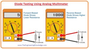
- The property of a proper operating diode is that it shows a large value of resistance for reverse biasing and during forward biasing very less resistance to flow of current.
- The diode that is defective will have a large value of resistance during reverse biasing and forward biasing.
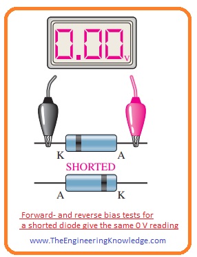
- While diode that is shorted has a small value of resistance during reverse biasing and forward biasing conditions.
- The most common fault that diode has is a failure of a diode.
DMM Diode Test Position
- Digital multimeter has the ability to perform diode tests. In the below figure multimeter is shown for diode testing.
- When a diode is connected with the multimeter for testing multimeter provides enough value of the voltage to make diode forward biased and reverse biased.
- These voltages depend on the type of multimeter normally the value of these voltages is 2.5 to 3.5 volts.
- To show different conditions of diode during a test multimeters screen is used.
Working Diode Testing
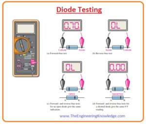
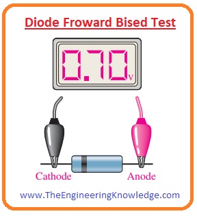
- In the below figure you can see that the red terminal of a multimeter is attached with the anode and black terminal of a meter is connected with the cathode and diode is reverse biasing condition.
- If the diode is in good condition then there will be a reading of 0.5 to 0.9 volts.
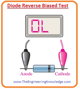
- In below figure diode is in reverse biasing condition negative terminal of the battery is attached with the anode and positive with the cathode.
- You can see there is no reading ‘OL’ is shown in below figure. Some meters some time show some value of voltages in the reverse biasing condition these voltage values are the internal voltage of meter.
Defective Diode Test
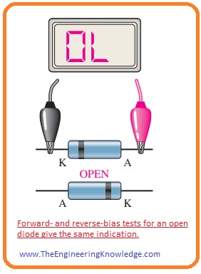
- If a diode is defective than there will be ‘OL’ for both reverse biasing and forward biasing conditions.
- If a diode is short-circuited then the reading on meter will be zero volts for both forward and reverse bias conditions.
Checking a Diode with the OHMs Function
- Some digital multimeters do not have an option for diode tests and they can be used for testing by setting the nob of a meter at the OHMs range.
- When you perform a forward biasing test on diode than you will have a value of resistance that can change according to a battery of meter.
- Some millimeters do not have enough value of voltage for OHMs range setting to forward bias the diode so you will have to take a reading by increasing the range of some Ohms to thousand Ohms.
- During a reverse test of the proper or good diode, you will see ‘OL’ on the meter as it is very difficult for a meter to calculate the resistance during reverse biasing of a diode.
- Though you can not get a precise reading in reverse biasing and forward basing condition on a meter but the relative value on meter explains about the reading you may require.
- The evaluation of some hundred to some thousand ohms for forward bias is comparatively less compared to the value of reverse biasing resistance that shows that diode is in good condition.
- The rale resistance offered by the diode in forward biasing is less than the one hundred.
Diode Testing Using Analog Multimeter
- Friends, now we use an analog multimeter to test the diode.
- There are some steps are for the use of the analog meter to test the diode.
- First of all, choose the position of selector switch at resistance mode.
- Attach cathode of diode with the negative terminal of the meter.
- Anode of the diode connects with the positive terminal of the meter.
- Then observe the resultant reading on the screen of the meter.
- The reading for these 4 steps is very less because the diode is in forward biasing condition.
- The current flowing in this state is larger.
- Fro this we can conclude that if reading is not according to our requirement than the diode has some faults.
- If the resistance value is very less than the diode is fine and you must now perform the reverse biasing test. The steps for this test are explained here.
- Attach a negative terminal of the meter with the anode of diode and positive terminal of the meter with the cathode.
- After that observe the readings on the screen of the meter.
- In this connection, there will be a large value of resistance on meter. It is due to the reverse biasing condition of the diode.
- In reverse biased condition very less amount of current flow through the diode.
- If the value on the meter is less than diode is not good and if value shown on meter is high than diode is in proper working condition.
Related Posts
- Current Regulator Diode
- Zener Diode
- Step Recovery Diode
- PIN Diode
- Schottky Diode
- Photodiode
- Varactor Diode
- Diode
- Zener diode Applications
- Laser Diode
- LED
So friends that is a detailed post about diode if you have any questions about this post ask in comments. Thanks for reading see you in next post.





Very nice post. I just stumbled upon your blog and wished
to mention that I’ve truly enjoyed browsing your blog posts.
In any case I’ll be subscribing on your feed and I’m hoping you write again soon!
This is really interesting, You are a very skilled blogger.
I’ve joined your feed and look forward to seeking more of your
wonderful post. Also, I’ve shared your website
in my social networks!