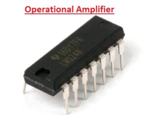
 Hello readers welcome to the new post. Today we will discuss Difference Between An Operational Amplifier and Comparator. From Integrated Circuits , what distinguishes operational amplifiers from comparators—which seem similar or have similar drawing symbols—and how can you tell them apart in real-world
settings?
Observe their internal difference diagram first:
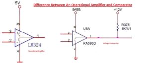
The output circuit distinguishes the operational amplifier from the comparator, as can be seen from the internal diagram.
The comparator utilizes a single transistor with the collector linked to the output and the emitter connected to ground, whereas the operational amplifier uses a two-transistor push-pull output. The comparator needs an external pull-up resistor that is equal to the transistor’s collector resistance from the positive power supply wire to the output terminal.
Operational amplifiers can be employed in nonlinear signal voltage comparisons or linear amplification circuits (negative feedback) (open loop or positive feedback).
The linear amplifier circuit cannot use the voltage comparator; it can only be used for signal voltage comparison (the comparator has no frequency compensation). Both can be used to compare signal voltages, but comparators are made to be rapid switches
with shorter delays and faster slew rates than op amps.
Operational Amplifier
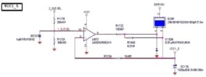
This is a common linear amplifier circuit found in motherboard circuit diagrams. Typically, a voltage regulator circuit uses it. It is equal to a three-terminal voltage regulator using a transistor when using a negative feedback circuit, although it is more adaptable to use.
As displayed below:
Knowing which of two signals is stronger or when a signal surpasses a certain voltage is often important (for voltage comparison). An operational amplifier can be used to accomplish this function in a straightforward circuit. The output is high when the V+ voltage exceeds the V-voltage. output low level when V+ voltage is lower than V- voltage.
As displayed below:
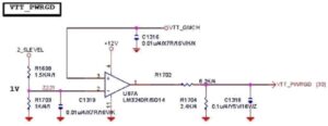
Examine the circuit. The resistors divide the 2.5 volts to provide a 1 volt input to the V- terminal. The input to V+ is the bus voltage, which is typically 1.2 volts. Currently, the CPU power management is receiving a high level of output since the V+ voltage is greater than the V- voltage. The EN enabling pin of the chip. If the bus voltage is not output or falls abnormally below 1 volt, the output is low because the V+ voltage is currently lower than the V- voltage.
Voltage Comparator
When the voltage of the comparator's non-inverting terminal (V+) is greater than the voltage of its inverting terminal (V-), the output transistor is activated and the output is grounded at a low level. Conversely, when the voltage of the non-inverting terminal is lower than the voltage of the inverting terminal, the pull resistor's power output is increased. As shown below:
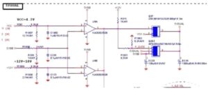
Investigate the circuit. The voltage split by the voltage dividing resistor when the comparator U8A above has a VCC output is input to the non-inverting terminal (V+) and is higher than the voltage input to the inverting terminal (V-) after 5VSB is divided. the internal transistor is turned off, the pull-up resistor outputs the power supply 12 volts, the N-channel field transistor Q37 is turned on, and the output VCC 5 volts. At the same time, the comparator U8B below has its internal transistor turned off because the voltage across its non-inverting terminal is higher than its inverting terminal. The P-channel field transistor Q293 is turned off at the same moment. In
contrast, the internal transistor is activated when the voltage at the inverting terminal is higher than the voltage at the non-inverting terminal, the pull-up power supply 12V is reduced to a low level, the N-channel field transistor Q37 is turned off, and the P-channel field transistor Q293 is activated simultaneously, outputting 5VSB. This is a 5VDUAL producing circuit (if not mentioned, general dual 5V refers to a +5, -5V power supply and 5V Dual refers to the dual +5V voltage). Operational amplifiers often do not require pull-up power sources in practical applications, but comparators do.
the essential difference between an op amp and a voltage comparator
| Operational Amplifier | Comparator |
|---|---|
| Amplifies the difference between two input voltages | Compares two input voltages and provides an output indicating which one is higher |
| Has a high gain, high input impedance, and low output impedance | Has a high gain and high input impedance |
| Used for amplification, filtering, oscillation, and many other applications | Used for decision-making applications such as threshold detection, window comparators, and hysteresis |
| Typically operates in the linear region | Typically operates in the saturation region |
| Can output both positive and negative voltages | Outputs a binary logic signal (high or low) |
| Feedback is used to control the gain and performance | Feedback is not typically used |
| Can be used to create comparators | Cannot be used to create operational amplifiers |
(1) The closed-loop characteristic is the primary distinction between the comparator and the amplifier Since the majority of amplifiers operate in a closed-loop mode, it is necessary that they be incapable of self-excitation after the closed-loop. The majority of comparators aim for speed when operating in an open-loop mode. The comparator cannot typically be used as an amplifier,
however, in the event of very low frequency, the amplifier can totally replace the comparator (pay attention to the output level).
This optimization narrows the range of closed-loop stability since the comparator is speed- optimized. Speed is decreased as a result of the op amp optimization for the closed-loop stability range. The best devices to carry out their functions are comparators and amplifiers in the same price range. It's possible to utilize a comparator as an amplifier and vice versa, just as an amplifier may be used as a comparator. To make it closed-loop stable, though, you might have to invest more than just an amplifier!
In other words, determining whether an op-amp is being used as a comparator or an amplifier requires examining the circuits level of negative feedback. As a result, the shallow closed-loop comparator might operate in an amplifier state without becoming stimulated. However, numerous testing must be carried out to guarantee that it is stable under all product-related operating circumstances! You must carefully weigh the expense and danger at this time.
(2) The comparator and operational amplifier are identical. Simply put, the comparator is an op amp used in open-loop, but it is specifically designed for voltage threshold comparison. The output edge increases upon comparison, and the comparison threshold must be precise. Alternately, the falling time should be brief, the output should adhere to TTL, CMOS, or OC standards, etc., the accuracy of the intermediate connection need not be precise, and the driving skills should differ. It is preferable to utilize fewer op amps as comparators in the design because most of them cannot attain full-scale output or the edge time after comparison is too long when used as comparators.
The difference between op amp and a comparator
Despite sharing the same symbols on the circuit diagram, the comparator and the op-amp are quite separate components that are typically incompatible. The variations are as follows:
1. The op-amp flipping speed is often on the order of us, whereas the comparator's flipping speed is quick, on the order of ns (except for special high-speed op amps).
2. The comparator cannot employ negative feedback, but the op amp can be coupled to a negative feedback circuit. Although the comparator also includes two input terminals for non-inverting and inverting signals, the circuit is unstable if coupled to negative feedback because there is no internal phase adjustment circuit. The key factor causing the comparator's superior
speed versus the op amp is the absence of an inbuilt phase correction circuit.
3. The operational amplifier's output stage typically uses a push-pull circuit with a bipolar output. Since open-collector structures make up the majority of comparator output stages, they require pull-up resistors, have a unipolar output, and are simple to integrate into digital circuits.
4. The comparator’s output, an open-collector (OC) structure, needs a pull-up resistor to be able to output current outside (LM339 and LM393). Op amps have push-pull output stages with symmetrical source and sink capabilities. Additionally, there are many intermediary steps and no internal frequency adjustment to speed up the comparator’s response time. A compensation
circuit is added by the op-amp to accommodate the linear region's needs. Since op-amps require comparators, LM339 and LM393 are not appropriate.


