 Hi friends, I hope all of you are fine. As you already know we have started a series of PLC articles. In the last lecture, we discussed a detailed article on the working principle of plc. In today’s tutorial, I am going to explain to you about detailed article on input and output connections of plc. The last tutorials related to plc have provided you a lot of knowledge about plc working and its parts.
Inputs and output connections of plc are main things that every plc operator should know. If he does not have knowledge about connection than he will not be able to use it. So this article is very important for new learners of plc. It helps them to how they can use plc if they know inputs and outputs terminals of plc. So let’s get started with a Describe the input and output section of PLC.
Describe the Input and Output Section of PLC
- The input and output section of a PLC is the unit with which all field instruments are associated and offers the interfacing among them and the plc processor.
- The fixed plc module has input and output connections already constructed while modular plc modules use exterior input and output units which plugged with the PLC.
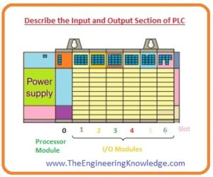
- In the given diagram a rack-based Input and output unit created by discrete input and output components.
- Input interfacing units receive signals from the instrument or processing component and change them into signals which can be used by the plc controller.
- Output interfacing units change controller signals into exterior signals that work to govern the process.
- A typical PLC has space for numerous input and output components, which allows it to be modified for specific use by picking the suitable units.
- Every opening in the frame has capacity to accommodate any category of input and output unit.
- The input and output scheme offers to interface among the wired pieces of machinery in the field and the processor.
- The input interface permits status information about processes to be transferred to the CPU, and thus allows the CPU to communicate operating signals through the output interface to the process devices under its control.
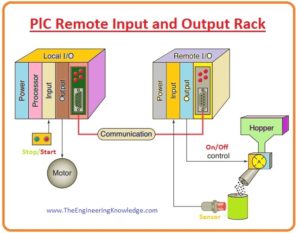
- A logic frame is an address capable element containing 128 input connection and 128 output connections points.
- A-frame uses 8 (eight) words (one word is equal to 2 bytes) in the input appearance stand folder and 8 words in the output appearance stand folder.
- A word in the output appearance stand file and its equivalent word in the input appearance stand folder are named as input and output group.
- A-frame or rack can be comprised of a maximum of eight input and output groups (starting from o to 7) for up to 128 distinct input and outputs.
- It can be more than one frame in a framework and more than one frameworks in a rack.
PlC Remote Input and Output Rack
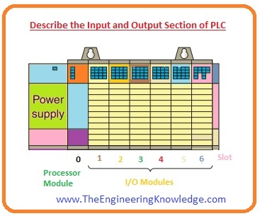
- Like other many advantages, one of the best advantage of plc is that it has capability to move the input and output components near the field instruments in order to lessen the quantity of cabling required.
- The CPU obtains indications from the distant input units and refers indications back to their output units by the communicating unit.
- A frame is known as a distant frame when it is situated away from the CPU unit.
- To connect with the CPU, the distant rack usages a distinct system of communications.
- Every distant rack needs a single position digit to differentiate one from other racks.
- The distant racks are connected to the resident frame by a communications unit. Wires join the units with one another.
- If we use fiber optic for connection among the processor and input, output rack it is likely to work inputs and outputs plugs from distances larger than twenty miles with no loss of voltage.
- While if we use Coaxes wires for connections it will not work for larger than two miles.
- Fiber optics will not get noise distortion produced by neighboring high power lines or apparatus usually establish in an industrial atmosphere.
- While coaxes cable easily gets this type of noise and cause distortion in sending and receiving signals.
Addressing of PLC
- The storage network of plc stores the material about location of the input and output.
- To retain path of all these material, it usages a scheme which known as addressing.
- An address is a tag or integer which designates where a definite part of info is positioned in storage of plc.
- It is like our house address where we live in our city, an instrument’s or a portion of information address says where info about it exists in the memory of plc.
- If plc wants to get information about any field instrument, it will just get its resultant address position.
SLC 500 Controller Addressing Format
- The address is used by the CPU to recognize where the expedient is situated to observe or govern it.
- In count, there are certain ways of joining field cabling on the input and output unit covering.
- Linking the field cabling to the input and output covering permits tranquil stoppage and re-joining of the cabling to alteration units.
- Lights are also attached to every unit to specify the ON or OFF rank of every input and output circuitry.
- Maximum output units also have illuminated fuse.

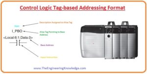
Control Logic Tag-Based Addressing Format
- In the given diagram Control Logic tag built addressing arrangement is shown.
- In this picture, we use the tag to address different variables.
- In place of a fixed number arrangement, the tag label itself recognizes the statistics.
- The field instruments are allocated tag designations that are a reference when the PLC ladder logic platform is established.
That is the detailed tutorial about the Input and Output Section of PLC, I have written each and every section of PLC. If you have any question ask in comments. See you in the next tutorial PLC Discrete Input and Output Devices.
I also have uploaded some related articles to plc you read them for further learning.


I likewise believe thence, perfectly written post! .