Hello, readers welcome to the new post. IN this post we will discuss the DC Motor Speed Control Project. The dc motor is an electrical machine that is used to convert electrical energy into mechanical energy. Its main parts are rotor-stator armature windings and stator windings. It is used in different applications such as industries machines railways and homes.
In this post, we will discuss the project that will help us to control the speed of dc motor. In this project, we will use NE555IC which is the main component for this project to regulate the motor speed. This integrated circuit and all other elements used in this project are positioned on the PCB boards that are designed by the PCBWAY. Looking for a customized PCB to order your PCB? And worried about the quality and price of PCB board? PCBWay is a good choice to order custom PCBs and other PCB boards. With ten years of experience in PCB prototyping, they provide you with the best PCB for your project. So to order your custom PCB, visit PCBWay. So let’s get started

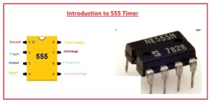
Introduction to NE555IC
- The 555 is an integrated circuit timer that is used in different types of applications such as timer, delay creation pulse production, and oscillator.
- It comes with two 556 and four 558 timing circuits in one unit. It was first time used in 1972
- Its operating volts lie between plus five volts to plus eighteen volts.
- Two hundred milliamps current loads current
- Its duty cycle can be varied and the maximum power dissipation for a single unit is six hundred milliwatts.
- It works in three modes of operation first one is A stable, monostable, and Bistable
- It comes with eight pinouts
- It is created through different manufacturers in low power and bipolar CMOS configuration.
- Its billions of components were created in 2003.
- Its structure consists of twenty-five transistors two diodes and fifteen resistances in one module.

DC Motor Speed Control Project
- The components used for the creation of these projects are described here.
- NE555 IC
- Potentiometer
- Capacitors
- Resistors
- Diodes
- Transistors
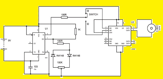
- The work of potentiometers is to change the speed of the motor. With the changes in the duty cycle of there is an increment in the speed of the motor. The input and output signals can be seen by connecting the oscilloscope with the PCB board designed by the PCBWAY.
- The feature of this circuitry is that has a simple structure and is preferred for fewer power motors applications.
- In this project, the 555 timers is operating in the stable multivibrator module generating the square waves.
- For regulation of duty cycle of 555 timer, there is the implementation of 100-kilo pot.
- The control terminal of 555 timers is linked to the one hundred nenoFarad capacitors that help to eliminate the noise.
- The active-low pin number four of the timer is linked to Vcc which helps the undesired reset of output.
Applications
- The main applications of this project are listed here
- It is employed in conveyor belts, escalators for the reduction of power losses.
- It is also employed in pumps and blowers to regulate the energy flow.
That is all about the DC Motor Speed Control Project. I have explained all details about the speed control of dc motor through use of 555 timers. If you have any further queries let me know. Further, I want to explain the PCB board used in this project is created by the PCBWAY which is well known and famous PCB creator and designer that helps to make different projects and components. So if you have to make any projects and design PCB must consider these PCB suppliers will help you to offered reliable and high-quality boards in reasonable prices. Thanks for reading have a nice day.


