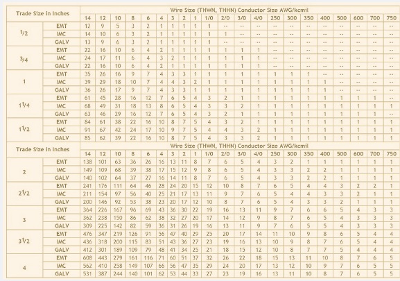
Standard conduit fill charts are defined based on the National Electrical Code. That conduit fill chart comes with details for a larger number of conductors existing in the conduit based on a 40 percent fill limit. Normally, the standard is more than 2 conductors.
The conduit fill chart gave details for the highest wire quantity that can safely pass through the sizes and types of circuits according to the National Electrical Code (NEC). In this post, we will cover details for conduit fill and conduit fill chart-related features. So let’s get started.
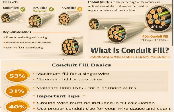
Definition of Conduit Fill
- Conduit fill is basically a cross-section of conduit that has cables. Which is measured as conduit area percentage. The conduit fill permitted value according to the National Electric Code (NEC) is defined according to the wire external diameter and the internal conduit diameter.
- By getting details of these numbers, we can use conduit fill values for determining installation fulfillment requirements of circuits.
- For the conduit fill chart and calculator, we needed some factors for consideration.
- Conduit type, size, diameter, wire type, size, and diameter, with the number of wires.
Conduit fill Conductor Materials
- for finding accurate conduit fill details of conductor materials based on uses. different materials used for different applications. Commonly used conduit materials are as
HDPE
- High-density polyethylene is a plastic type used for making conduit for houses and telecommunication sector cables. This material has high resistance to ultraviolet effects and different chemical and corrosion effects.
Nylon:
- Nylon has resistance to abrasion and solvent resistance with good weather resistance. Different machines and vehicles preferred molded nylon conduit
PVC-coated metal
- Conduit having a base metal provides high strength. PVC-coated metal conduits are employed for machines and wiring used in industries.
Conduit conductor materials
Commonly used conductor materials are as
THHN
- THHN is a wire that comes with nylon coated with a rating temperature of 194°F for different conditions like moisture and dryness. This wire is part of the machining tools and control circuits.
THHW
- THHW wires employed for branch circuits and feeders, and to manage temperature conditions: 167°F for dry conditions and 90°C.
THWN
- This conductor is part of control circuits, machine tools, and wiring since it easily manages up to 167°F for moisture and dry conditions.
THW
- THW part of the branch circuits home wiring with 167 degrees Fahrenheit
How to Calculate Conduit Fill? Detailed steps
There are some points involved for calculating conduit fill percentage, as explained here.
Number of Conductors
- First of all, find the number of cables needed to run in the conduit. During the calculation, future conductor installation was also considered, and space was left for connecting cables. During conductors’ calculations, they also included ground wires with the defined insulation needed for wires.
Measure Wire Cross-Sectional Areas
- Wire cross-sectional area is important for finding conductor space. For this purpose, get details of wire gauge insulation with wire in conduit.
- for measuring cross-sectional area, wire diameter, and square with 0.79. We can also find material diameter and wire gauge in the NEC guidelines.
- After measuring the cross-sectional area of all wires, add the resultant to get square inches of total cross-sectional area.
Conduit’s Minimum Space Calculation
- according to a certain value of fill percentage for the number of wires. Percentage details control jamming wires with the heating effect.
- • The NEC conduit fill chart defines high values of conduit fill percentages, like for a single conductor, 53 percent of the space used in the conduit. In two conductors, 31 percent, and more than 2 conductors, 40 percent, conduit is used.
Follow the National Electric Code (NEC).
- NEC also employs a conduit fill chart for minimizing further calculations. NEC gives accurate details of conduit fill in the chart. From the NEC chart, we can get details for wire gauges.
Conduit Bends
- Bends in conduit are also important factors for getting the right fill percentage. A larger number of bends makes conductor pulling difficult. Conduit fill percentage makes it difficult, so do not add bends more than 90 degrees.
- When the conduit is filled based on the given limit, use another conduit with a larger size. It avoids wire damage.
Conduit Fill Chart
- A conduit fill chart is basically a reference table that gives details according to the number and cable sizes that exist in conduits.
- Through help and proper understanding of the chart, we can get the required conduit sizes for cables. Accurate conduit sizing helps the cable to be removed easily without damaging it and causing high heat.
- If we use an improper conduit size, it causes installation and safety faults. High-strain cables are affected due to overfilled conduits, which affect insulation, cause high resistance, and also increase the risk of fire.
- If we have an undersized conduit, it causes a difficult installation process and also damages cables.
- Overfilled conduits with applied cable strains also cause effects on air flow. Due to ventilation, cables become overheated, and insulation is damaged.
Conduit Fill Chart (40% Fill Rule)
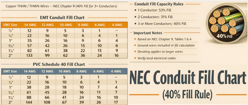
EMT Conduit Fill Chart (Copper THHN/THWN)
| EMT Size | Max 12 AWG | Max 10 AWG | Max 8 AWG | Max 6 AWG | Max 4 AWG |
| ½” | 9 | 5 | 3 | 1 | – |
| ¾” | 16 | 10 | 6 | 4 | 1 |
| 1″ | 26 | 16 | 9 | 6 | 4 |
| 1¼” | 42 | 26 | 15 | 10 | 6 |
| 1½” | 61 | 38 | 22 | 15 | 9 |
| 2″ | 99 | 62 | 36 | 24 | 16 |
PVC Schedule 40 Conduit Fill Chart
| PVC Size | Max 12 AWG | Max 10 AWG | Max 8 AWG | Max 6 AWG | Max 4 AWG |
| ½” | 9 | 5 | 3 | 1 | – |
| ¾” | 16 | 10 | 6 | 4 | 1 |
| 1″ | 28 | 18 | 10 | 7 | 4 |
| 1¼” | 45 | 28 | 16 | 11 | 7 |
| 1½” | 66 | 41 | 24 | 16 | 10 |
| 2″ | 108 | 67 | 39 | 26 | 17 |
PVC Schedule 80 Conduit Fill Chart
| PVC Size | 14 AWG | 12 AWG | 10 AWG | 8 AWG | 6 AWG | 4 AWG |
| ½” | 10 | 7 | 4 | 2 | 1 | – |
| ¾” | 18 | 13 | 8 | 5 | 3 | 1 |
| 1″ | 30 | 22 | 14 | 8 | 5 | 3 |
| 1¼” | 48 | 35 | 22 | 13 | 9 | 5 |
| 1½” | 69 | 51 | 32 | 19 | 13 | 8 |
| 2″ | 114 | 85 | 53 | 31 | 21 | 13 |
Rigid Metal Conduit (RMC) Fill Chart
| RMC Size | 12 AWG | 10 AWG | 8 AWG | 6 AWG | 4 AWG | 2 AWG |
| ½” | 8 | 4 | 2 | 1 | – | – |
| ¾” | 14 | 9 | 5 | 3 | 1 | – |
| 1″ | 23 | 14 | 8 | 5 | 3 | 1 |
| 1¼” | 37 | 23 | 13 | 9 | 5 | 3 |
| 1½” | 53 | 33 | 19 | 13 | 8 | 5 |
| 2″ | 86 | 54 | 31 | 21 | 13 | 8 |
NEC Conduit Fill Percentage Rules
Conductors in Conduit | Max Fill |
| 1 conductor | 53% |
| 2 conductors | 31% |
| 3 or more | 40% (standard use) |
Read also
- Wrench Sizes Chart in Order from Smallest to Largest
- Wire Ampacity Charts | Wire Gauge Chart
- R407A Pressure-Temperature Chart
- R-290 Propane Refrigerant PT Chart