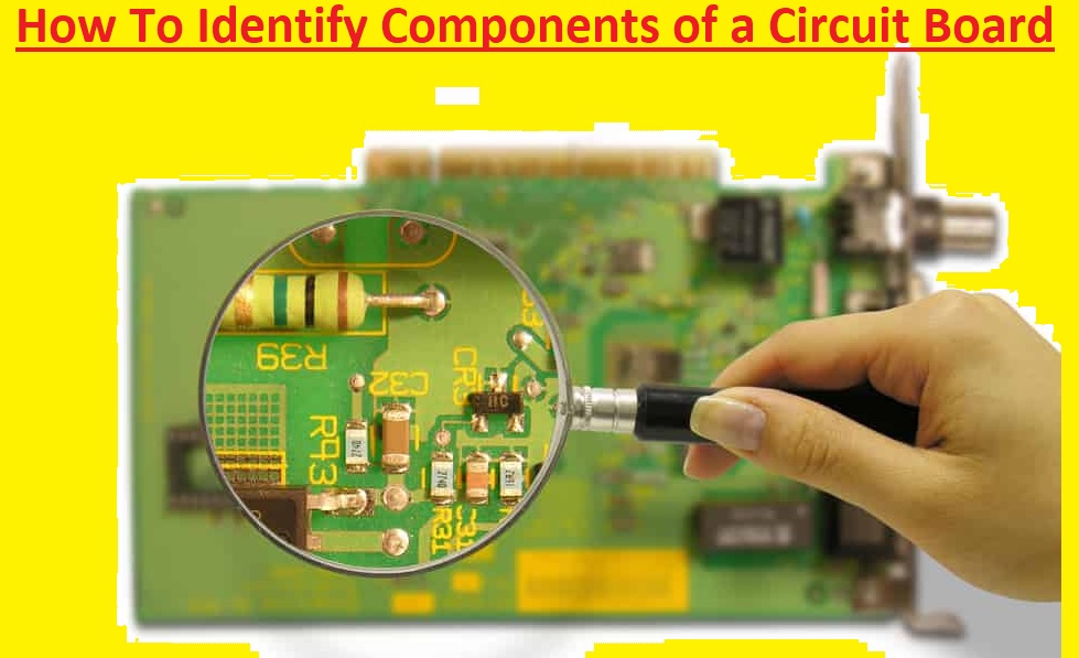
Hello, readers, welcome to the new post. In this post, we will learn How To Identify the Components of a Circuit Board. PCB boards are the main component of electronic projects, and the device comes with a different component that operates to have an accurate function. The knowledge of these components is required for preparing troubleshooting and modification of electronic devices. In this post, we will discuss different PCB components and learn how to identify components of a circuit board. Let’s get started with an introduction to the components of a circuit board.
Introduction Circuit Board Components
Circuit boards, also called printed circuit boards, are thin boards created using non-conductive materials like fiberglass or epoxy resin. The board has many component configurations to make circuits, like active and passive components, connectors, and power supplies. All these components perform different functions.
Types of PCB board
The main types of PCB based on construction are
Single side board:
This board has a conductive layer on a single side for component connection.
Double-sided circuit boards:
This board has conductive layers on both sides to make circuits.
Multi-layer circuit boards:
These boards have multiple layers where many components can connect to make projects.
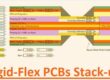
Circuit boards are made with the use of many materials. Base materials are made with the use of rigid or flexible insulating substrates, like FR4 or polyimide. The copper foil used for conductive layers is etched to make a circuit pattern.
PCB Circuit Board Layers
- Copper Layers: These are conductive layers created with the use of copper and etched to make a required pattern and have an electrical connection between components.
- Solder Mask: It is a protective layer that covers copper traces and a safe board from short circuits and helps the soldering process through expansion-required parts of component connections.
- Silkscreen: It offers visuals of component position, like leveling, and symbols where components are connected.
- Insulating Layers: This layer is made with FR4 or polyimide, and separated copper layers throughout others save short circuits and give the board mechanical strength.
Circuit Board Component Reference Designators
| Component | Designator Prefix |
| Resistor | R |
| Capacitor | C |
| Inductor | L |
| Transistor | Q |
| Diode | D |
| Integrated Circuit | U or IC |
| Connector | J |
| Relay | K |
| Switch | S or SW |
| Transformer | T |
| Crystal/Oscillator | Y |
| Fuse | F |
Overview of Components and Parts of Circuit Board
.
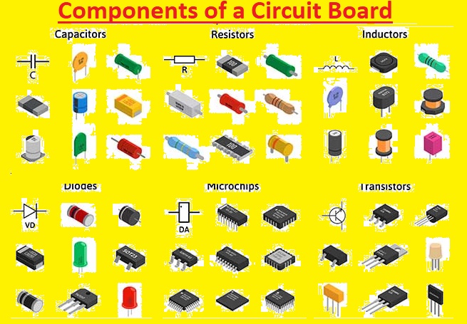
Resistors
The resistor is a very basic and simple component of the board. This component passes electric current to generate voltage and dissipates electric power in the form of heat. It has different material ranges and colors for defining their resistance value.
Transistors
The transistor is an amplifier component used as a switch or controls the signal on boards. Transistors come in different types, but commonly used is a bipolar transistor, which comes with a base emitter and collector pins.
Capacitors
Capacitors are important components like resistors. It stores changes in the board and releases them when high power is required in the circuit, normally through getting reverse charges in two layers that are parted through insulation materials.
Inductors
Inductors are like capacitors, and they store energy in the form of a magnetic field when current passes through them. It is used to block the signal on the board, like interference from another component or device.
Transformers
The transformer is used to transfer electrical energy from one circuit to another through increases or decreases in voltage level.
Diodes
The diode is a pin component that converts AC into DC and allows the current in one direction, not in the reverse direction. It can be used to block current flowing in the wrong direction, which can affect the board and device. A famous diode is an LED that releases light. Commonly used types of diodes are
- Tunnel diode
- Zener diode
- Rectifier diode
- Schottky diode
- Constant-current diode
- Shockley diode
- Silicon-Controlled Rectifier (SCR)
- Photodiode
- Bridge rectifier
- Varicap diode
Sensors
This device detects changes in environmental conditions and produces electrical signals that result in the change detected, that is sent to the components in the board. Sensors transform elements like light motion, air quality, or sound in electrical energy such as transducers.
Silicon-Controlled Rectifier (SCR)
Integrated Circuits
It is the brains of the wider circuit. The circuit is covered in black plastic that can have different shapes and sizes and visible contacts whether they are leads of the body.
Crystal Oscillators
Due to that, they are used as timers for controllers or in-quarter wristwatches.
Switches and Relays
The switch is a power button for controlling the current passing in the circuit by switching between open or closed circuits. Both have similar appearances and come with different types like lider, rotary, push button, lever, toggle, and key switch.
A relay is an electronic switch worked through a solenoid that becomes like a temporary magnet when current passes through it. it works like a switch and can amplify small currents to larger current
PCB Mechanical Components
This component type uses a mechanized process that is based on the metal used. Normally mechanical PCB components are created with aluminum, but some are made with steel, copper, and bronze.
The difference between electrical and mechanical components is that, contrary to electrical that offers electrical functions, mechanical components do not have. The primary function of mechanical components is to offer more secondary support to the PCB.
How the electrical components work
The working of electrical components is based on electrical energy. They are connected on board with the use of surface mount technology or through-hole technology. Both processes are used in designs and board configuration. Electrical components are solder directly mounted on board through wires that pass through holes in boards.
How to Identify the Through Hole Components
The THT or through-hole technology is the main process of technology used to manufacture of board.
In this technology, components are connected on board through large and longer leads. These leads come with openings and holes to pass through them to help the board configuration.
A component connected with a pad through solder is an example of a THT component.
THT components on board can easily be identified, but SMT components are not found easily.
What are SMT components?
- These PCB components are configured on the PCB board. Contrary to THT components, they do not have holes to make connections.
- These components can be identified through shorter leads and do not have holes; there are some points to find SMT components.
- These components have shorter leads.
- Not come with holes
- They are based on soldering of surfaces to copper pads at the top of boards.
How are components connected in a PCB?
Components are configured on non-conductive boards and connected with small pathways called traces. These traces help electrical components over the board to work through passing current. PCB board comes with small holes that are drilled where every component is connected.
Through-hole components are connected through wire leads passing through the board and soldered to traces on another side. In the SMT technique, components are connected through leads to copper traces on the same side. The board can use both techniques for connections.
Learn How PCB Circuit Board Soldering Guide for Beginners
Faqs
What does z mean on a circuit board?
- The impedance symbol is a Z letter and is measured in units of ohms in complex form. Accurate resistors have resistance but not reactance. Perfect inductors and perfect capacitors come with reactance but no resistance.
How do I test a diode?
- The diode is tested by measuring voltage loss over the diode when it is forward-biased. The forward-biased diode works as a closed switch, enabling the current flow. The multimeter diode test mode generated a small voltage between testing leads.
How do I identify electronic components?
- Electronic components come with markings on their structure or packaging to show their value or part number. From the certain markings on the body of the component, we can identify the component. Such as in color-coded resistors, the bands of color have values of resistors.
How do I choose PCB components?
- The common method for choosing the main components to use is to define the threshold of variance, like 80 percent, and then choose components that produce the cumulative sum of variance as possible to the threshold.