

 Hello friends, I hope you all are doing great. In today’s tutorial, we will have a look at Common-Gate FET Amplifiers. The common gate field effect amplifier configuration is associated with the common base configuration of BJT. Similar to the common base arrangement the input resistance of common gate is also less. It is different to the common source and common drain configurations that have a large value of input resistances.
This circuit configuration normally used as a voltage amplifier. The source of FET in this configuration is operating as input and drain as output gate terminals are connected with both terminals or common point. In today’s post, we will have a detailed look at its circuit, working and some other related parameters. So let’s get started with Common-Gate FET amplifiers.
Common-Gate FET Amplifiers
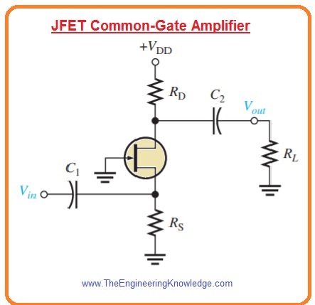
- The self-biased common gate amplifier configuration is shown in below figure. The gate is attached to the ground.
- The input voltage is given to the source through bypass capacitor C1.
- The output is taken out from gate through capacitor C2.
Voltage Gain
- The voltage gain from source to drain is given as.
Av=Vout/Vin=Vd/Vgs=IdRd/Vgs=gmVgsRd/Vgs
Av =gmRd
- Here Rd=RDΙΙRL
Input Resistance
- As we discussed above that input resistance of common gate configuration is less which can be find as.
Iin = Is = Id = gmVgs
- Vgs is equals to input voltage
Vin = Vgs
- So input resistance at source will be.
Rin(source) =Vin/Iin=Vgs/gmVgs
Rin(source)=1/gm
Cascode Amplifier
- The main applications of common gate amplifier configuration is the cascode amplifier usually used in radio frequency applications.
- In cascode amplifier common source and common gate amplifiers are attached in a sequence.
- The BJT can can also be used to make cascode amplifier with the use of common base and common emitter configuration.
- In below figure JFET cascode amplifier circuit configuration is shown.
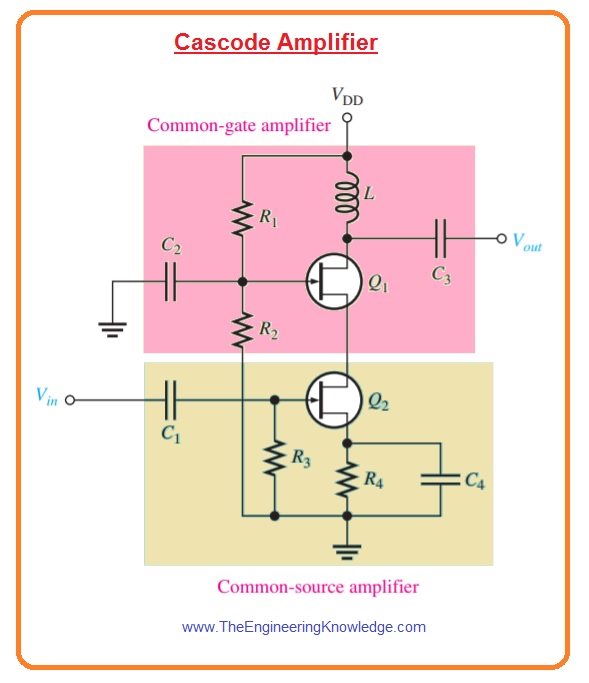
- The input stage is common source amplifier ad load is common gate amplifier attached in drain circuitry.
- The cascode amplifier consisting of JFET gives large value of input resistance and significantly decreases capacitive effect to operate at large frequency value than common source amplifier operating alone.
- Internal capacitance that exits in each category of transistor become sufficient at large frequency and decreases the gain of inverting amplifier.
- The ist stage is common source amplifier which inverted the signal.
- Though gain is less due to less input resistance of common base amplifier which running it.
- Due to that effect of internal capacitance on the large frequency response is very less.
- The 2nd stage of circuitry is common gate amplifier which does not invert the signal so it has large gain without decreases the large frequency response.
- The use of 2 amplifiers gives the best result of both circuitry, that cause in large gain, large input resistance and good large frequency response.
- The voltage gain of cascode amplifier shown in above figure is multiple of gain of both the common source and common gate stage amplifer.
- The gain is given by the common gain amplifier configuration.
Av = Av(CS)Av(CG)= (gm(CS)Rd)(gm(CG)XL)
- As RD of common source amplifier stage is input resistance of common gate stage and XL is reactance of inductor in the drain of common gate amplifier configuration the gain will be.
Av=(gm(CS)(1/gm(CG))(gm(CG)XL) =gm(CG)XL
- by supposing that transconductances of both transistor are almost same.
- From this equation you can see that voltage gain increases with the frequency since XL increases.
- As frequency is continuously increases finally capacitance effects become important sufficient to begin decreasing the gain.
- The input resistance of cascade amplifier is input resistance of common stage amplifier.
Rin=R3ΙΙ(VGS/IGSS)
So that is detailed post about Common-Gate FET Amplifiers if you have any question ask in comments. Thanks for reading. Have a good day.


Hi! May I know if R1, R2 and R4 should be calculated specifically like R3 too? If so, how do we calculate them? And how to calculate the capacitors? Thank you.