 Hello, readers welcome to the new post. Today we will discuss Adjustable Timer Circuit using 555. The timer is a very commonly used device that is the main part of different electronic devices such as washing machines, ovens, etc. Timer helps to operate load according to requirements as in washing machines you can set time for your cloth washing, rinsing and water removal. Different loads can be regulated through manual control as when the load is on and after getting the required results load will get off.
In this post, we will discuss the adjustable timer circuit where 555 timers is used as the main component that this project is created on the PCB board get from the PCBWAY.
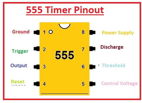
Introduction to 555 Timer
- The 555 timer is an integrated circuit that is used in different circuits such as timers, delay, and pulse generation also employed for oscillators.’
- Its counterparts are 556 and 558 timers in single packaging.
- It was first used in 1972. There are many manufacturers who create this device.
- Usually, there are twenty-five transistors, fifteen resistors and two diodes located on one board.
- This board comes with eight leads that are a double inline package.
- Some modules of these categories like 556 come with fourteen pinouts and 558 has sixteen pinouts.
- Its temperature range where it works is between zero and seventy degrees Celsius.
- The voltage range for which it operates is 4.5 volts to 15 volts DC.
- Flip-flops, voltage dividers and comparators are configured on the board of this device.
normally used to offer a time delay where used. - Its operating modes are monostable, bistable.
- It consists of 3 resistors of five kilohms in series combination to voltage divider modules, known as 555 timers.
- It provides a larger value of current at the output terminal, so it is used for TTL operation
555 Timer Features
- Its operating volts are plus five and have the ability to operate for plus eighteen volts
- It comes in eight pins SOIC VSSOP packaging
- Its function temperature is seventy centigrades
- It has a value of trigger volts is 1.67 during operating states
- it uses three milliamperes current
555 Timer Applications
- It used in sequence timer circuits
- Used for accuracy of time
- Generates pulse
- PWM circuits use this component and used for time delay in different projects
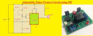
Adjustable Timer Project Circuit using 555
Project Components
- The components used in this project are listed here
- Battery
- Push Button
- Capacitor
- Resistances
- Variable Resistance
- Buzzer
- 555 Timer
- PCB from PCBWAY
- PCBWAY is one of the best PCB suppliers they offer free PCB boards for their users to get their different services and products that helps to enhance their features from outputs of different users. Their free PCB features help students have low budgets and make their projects with great features at low prices. Their free features can be used in any part of the world by any engineer either older or new to the field. This is a great feature for electronic lovers and persons how to keep buying PCBs through online services. Every user can avail of the free PCB features.
- From these features of PCBWAY, you can get any type of PCB such as HDI, standard, aluminum, flexible PCB rigid-flex PCB, high frequency, etc. You can also get high-precision laser SMD stencils and assembly services.PCBWAY is the one solution for all PCB-based services that’s why they offer quick turn and high quality services.
- Currently, they have seventy thousand plus active customers which is why their quality products and excellent services provide satisfaction to their users. With all features, you can get a full refund if you are not satisfied with any service. These features make PCBWAY the best in all services all over the world.
- Currently, this PCB supplier has introduced PCBWAY 5th PCB Design Contest must take part in this contest to win the highest prizes

Adjustable Timer Circuit using 555
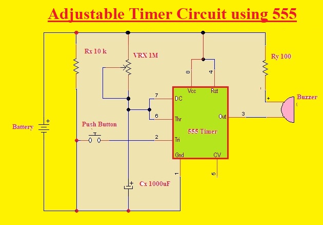
- In this circuit 555 timer IC is our main component it is used as a monostable multivibrator. For the monostable mode of 555 timer pulse of a certain length is generated by pressing the triggering button. The output pinout is at low til the button is pressed.
- After selecting the monostable mode connect the trigger pin of the timer to the ground through the push button. When we press the push button supply is given to the trigger pin in negative mode and the 555 timer start operation.
- Potentiometer VRx and capacitor parts of timer and connected to the power source battery. The discharge pin and threshold pin of the timer is linked to components of the timer. There is the use of ten-ohm resistance to linking the output of the circuit to the buzzer.
- The reset pin and positive supply pin of the timer are attached to the battery positive terminal and the ground pin is attached to the negative terminal of the battery.
- Through the use of a potentiometer output value can be adjusted and before using the circuit must set the output value
Adjustable Timer Applications
- Common applications of this circuit are listed here
- It is used for printers circuits to set the time for printing
- The operation of these circuits also for traffic lights that blink according to to set time
- It used for automatic lubrication modules
- It used in powerhouses for the control of electricity
- Industrial machines used this mode
- Used in exhaust fan switch
- It used in irrigation pump regulation
That is all about the Adjustable Timer Project Circuit using 555 all details has explained. If you have any queries ask in the comments. Thanks for reading have nice day.
Read also


