

Hi friends, I hope all of you are fine. As you already know, we have started a series of PLC articles. In the last lecture, we discussed a detailed article on PARTS of a PLC. In today’s tutorial, I am going to explain to you a detailed article on the working of a PLC. After reading previous articles about PLCs and their parts, I hope all of you have become well aware of PLCs and their parts. Now you can understand its working very easily.
In this article, we will discuss the detailed working of a PLC and its comparison with relay working. Also, we will discuss its modified operation and how we can modify it manually. So let’s get started with the working principle of PLC.
.
Working Principle of PLC (Programmable Logic Controller)
PLC meaning is the programmable logic controller. To learn about a PLC’s working principle, we discuss a simple example in which we study its manual process control, then relay control, and finally how we can control this process by PLC.
First of all, we discuss manual control or processes.
In the given diagram, we take an example of a motor control mixer. In this process we are using two sensors; the first one is temperature, and the other one is pressure.
These two sensors are connected with the motor, and their values have already been set.
When we start a motor with a manual push button, the motor mixes the liquid, and when the set values of temperature and pressure is reached, the connected sensor makes their contacts close and tells about process control. By knowing this we can start or stop our motor.
Motor Control by Using Relay
As we have discussed a manual method of motor control, now we discuss how to relay control of this process.
In the given relay ladder logic diagram, we can see that the motor will start working when both temperature and pressure switches are connected, or the motor will work when we press a push button.
Till now we have discussed motor control by manual and relay methods; now we have discussed this process: how we can control it by PLC.
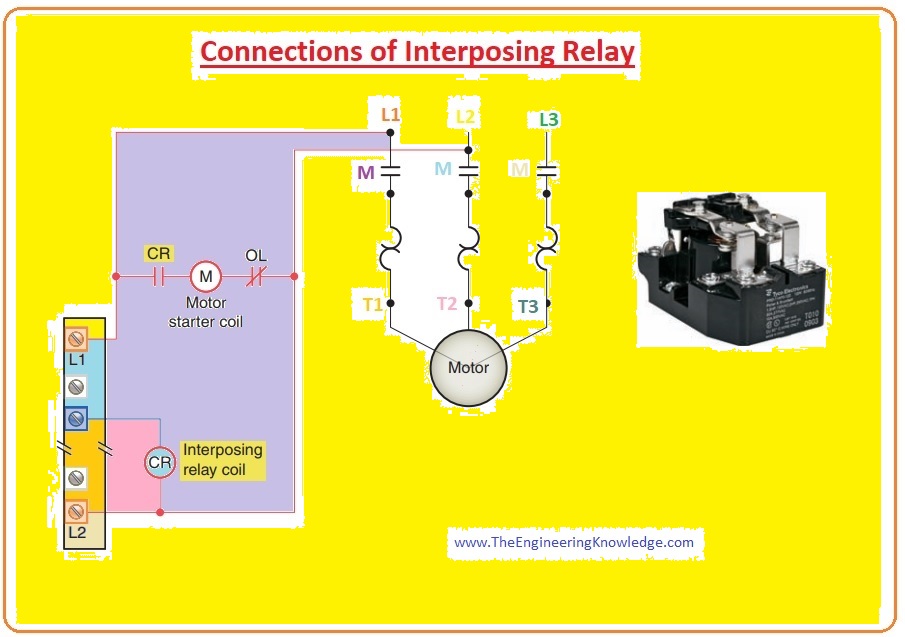
Working Principle of PLC
Now we discuss how we can implement plc for this process.
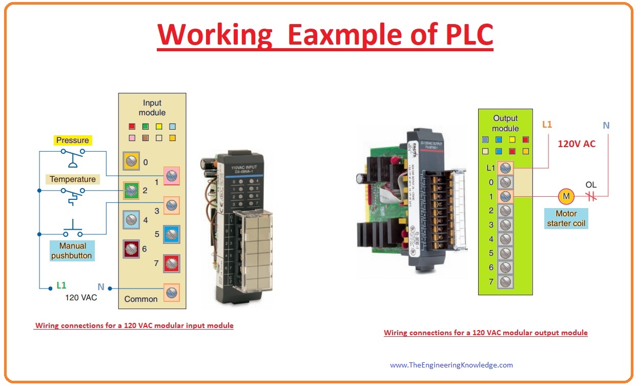
For plc, we are also using the same input components that we used in previous methods, like pressure, temperature switches, and push buttons.
These components are connected with the PLC input module connections, which are designed by the manufacturer.
In this example, we use a 120v AC module whose input connection is shown in a given diagram.
In this process, we also use the same output component, which is the motor.
This output device is also connected with the output module of the PLC according to the manufacturer’s output connections scheme.
Distinctive installing links for a 120V AC modularly arranged output unit are displayed in a given diagram.
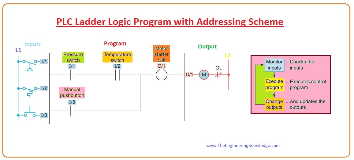
PLC Ladder Logic Program with Addressing Scheme
The PLC ladder logic program is built and fed into the storage of the central processing unit.
A distinctive ladder logic program for this procedure is displayed in a given diagram.
The arrangement used is similar to the arrangement of the wired relay ladder circuitry.
The discrete symbols in this circuit signify commands, while the numbering signifies the order position statements.
To give programming instructions to the controller, you feed these commands one by one in the CPU memory from the programming component.
Every input and output component will be assigned a special location address, which will allow the PLC to know about where it is physically connected.
The input and output addresses will be different for different manufacturing companies.
Commands are put in the user program part of the CPU storage.
Throughout the program scanning, the controller observes the inputs, implements the controller program, and varies the output consequently.
In the above diagram, we have discussed input and output configuration with the PLC; now we study how this program runs in the PLC.
How to Run a Program in a PLC
- For the program to work, the control is located in the running style or functioning sequence.
- Through every working rotation, the controller inspects the position of an input component, implements the operator program, and varies outputs consequently.
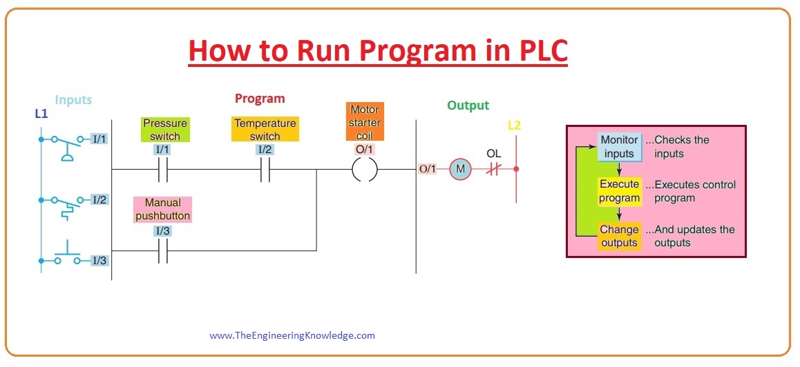
Every sign like this can be considered as a set of typically open connections. The sign () is used to signify a loop that, when energized, will close a set of links.
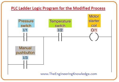
In the given ladder logic program below, we can see that the coil (O/1) will work when links (I/1) and I/2 are locked, or the coil will work when link I/3 is closed.
A PLC works instantly, which means when one program works, it also gives output at the time of implementation.
For the implementation of the operation, some steps are described here.
First of all, the pressure and temperature switches and pushbutton inputs are inspected, and their position is documented in the memory of the controller.
The open contact is stored in memory as 0, and the closed contact is stored as 1 (one).
Then ladder circuitry is monitored with every inner connection assigned as an open (o) or closed (1) rank according to its 0 or 1 conditions.
When the conditions of the input links offer logic stability from left to right along the ladder, the output coil storage position is assigned a logic 1 (one), and the output unit interfacing links will close.
When there is no logic continuousness of the program ladder, the output coil storage position is set to logic 0 (zero), and the output component interfacing links will be open (0).
The accomplishment of one round of this arrangement by the controller is named a scan.
The scan time, the time required to complete one rotation, delivers a measurement of the speed of reply of the Programmable Logic Controller (PLC).
Normally, the output storage position is reorganized through the scan, but the real output is not reorganized till the completion of the program scan through the input/output scan.
Working of Fixed PLC Modular
- In the last heading, we discussed how a ladder logic program is made and how it works. Now we discuss plc fixed modular connection and assembly of the ladder logic program.
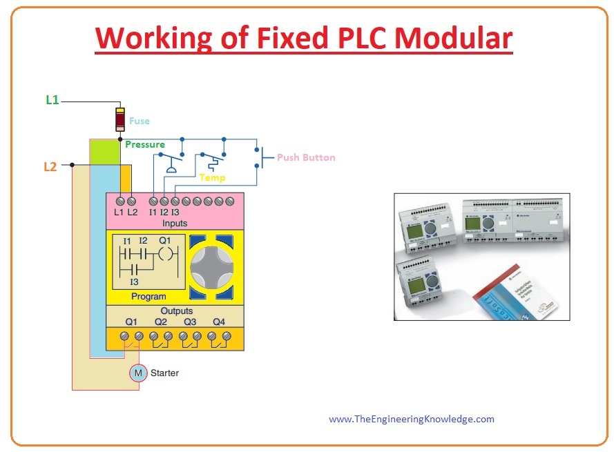
The given diagram shows the distinctive cabling essential to implement the process control arrangement by means of a fixed PLC regulator.
In this example, the plc controller furnished with 8 (eight) inputs and 4 (four) outputs is used to switch and observe the procedure.
The connection of this PLC module is described below.
Power lines consisting of fuses of definite voltage categories and levels are associated with the L1 and L2 connections of the controller.
The input field components like pressure and temperature switches and push buttons are connected by the wire among the L1 and I1, I2, and I3, which are the input terminals of the controller.
The motor starting coil links with L2, and in sequence with Q1, the relay output links to L1.
After this connection, we can input our ladder logic program by using the keypad on a controller and can see the program on an LCD display.
Guys, till now we have learned about the working of a PLC and its ladder logic construction. But sometimes we want to change or modify our ladder logic program, which we create using a PLC.
Can we change this circuit? Or can we modify it? For these questions, we discuss how we can modify PLC operation. We also discuss its comparison with relay logic. Meaning, what we should do if we want to replace the relay logic circuit.
How to Modify PLC Operation
- A PLC has many features, but one of the main features is that we can easily modify our written program.
- First of all, we discuss it in the case of relay ladder logic.
- Let’s suppose that we have to modify the process control circuitry that we discussed earlier.
- In a given diagram, we can see that alteration which has is if we want to control our process by only a temperature switch for this we have to change our wiring, which is a very difficult task.
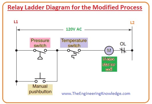
- But in the case of plc, we will just change the program which we had already made and nothing else.
- From this, we can observe that it is very easy to modify our program in plc but in the case of a relay, it is no easy task. Modification for PLC shown below.
FAQs
What are the industrial applications of PLC?
PLCs are used in different applications such as smart grid systems, power plants, manufacturing units, monitoring machine tools or equipment, building the system, and process control functions.
What is the PLC and its working principle?
The PLC is an industrial computer control system that monitors the condition of input devices and makes decisions based on custom programs to control the condition of output devices.
What is a PLC? Why is it used in industrial process control?
PLCs monitor and get data from input devices or sensors, process data, and trigger connected output devices for complete operation in industrial processes or machinery.
What is the function of a PLC in the industry?
In industries, manufacturers use PLCs for monitoring and automating production processes. PLCs are designed as industrial computers that can handle the conditions of an industrial environment.
Where are PLCs used in industry?
PLCs are used in different industries such as the steel industry, automobile industry, chemical industry, and power sector.
What is the basic concept of PLC?
PLC monitors machine inputs and makes accurate decisions based on the program and controls outputs to trigger machine and process automation. A PLC is created with input points or modules, output points, and a CPU.
That is all about the working principle of PLC if you have any questions about part of plc you can ask in the comments. See you in the next tutorial, Input and Output Section of PLC.




Very nicely explained Good
thanks dear
Incredible! This blog looks just like my old one!
It’s on a entirely different topic but it
has pretty much the same layout and design. Outstanding choice of colors!
I have read some good stuff here. Definitely worth bookmarking for revisiting. I wonder how much effort you put to make such a fantastic informative website.
Thanks , I’ve just been searching for info approximately this topic for ages and yours is the best I’ve came upon till
now. But, what in regards to the bottom line?
Are you certain about the source?
Like!! Great article post.Really thank you! Really Cool.
thanks for you best article
I read full text its helps me a lot