 Hello, friends welcome to the new post. In this post will have a detailed look at Introduction to Inverter. The inverter is a device that used to transform DC to AC in the electrical system. The common use of dc is in solar systems where generation occurs in dc so inverters are used to convert dc to ac. The main use of dc in the solar system since these generate dc.
The main function of an inverter is to convert dc to ac. The ac system can be used at home industries through the use of a grid system. In this tutorial we will cover basic fon inverts working operation and some other related parameters. So let’s get started with Introduction to Inverter.
Introduction to Inverter
- Currently, the very fast-developing area in power electronics is static frequency transformation the transformation of ac from a single frequency to ac at a new frequency through use of solid-state electronics.
- There are 2 methods used for the conversion of static frequency first one is the cycloconverter and the second one is rectifier inverter.
- The cyclo converter is a module used for the transformation of ac power from one frequency to another level of frequency. The rectifier-inverter is one of all transform ac power to dc after that, transform dc to ac at a new level of frequency
- 2 main parts of rectifier inverters are mentioned here.
- The rectifier to generates ac power
- An inverter to generates ac power through the dc power.
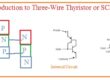
What is a Rectifier
- The simple rectifier circuitry transforming ac power to dc power will be discussed. Such circuitry has one issue through the motor control aspect their output voltage has a certain value for the applied voltage.
- This issue can be decreased by adding diode with combination to SCR
- The diagram shown below has 3 phase full wave rectifier circuitry consisting of diodes in the circuitry replaced by SCR.
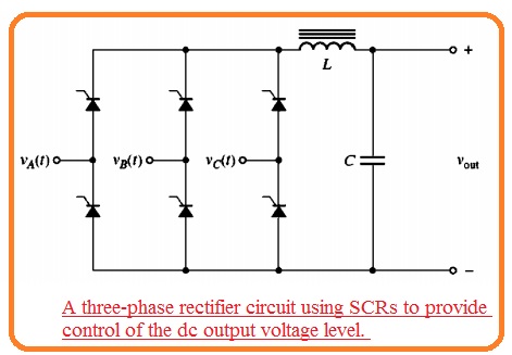
- The average dc output voltage through this circuitry relies on when the SCR gets triggered from the positive half cycle
- If this circuitry gets triggered at the start of the half-cycle, this circuitry will be like a three-phase full-wave rectifier with diodes. If the SCR is not triggered, the output voltage has zero volts.
- In case of any firing angle between zero to eighteen hundred at the signal. The dc output voltage will range from extreme and zero volts.
- When the SCR working in place of rectifier circuitry for control of the DC voltage output that output will has a large number of harmonics than the basic rectifier and a certain type of filter at the output are significant.
- The above diagram indicates an inductor and capacitor filter positioned at the output of the rectifier to make smooth of dc output.
External Commutation Inverters
- The inverters are categorized in 2 main types through the commutation method employed for exterior commutation and self commutation.
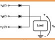
- External commutation inverters are inverters for which energy is needed to off the SCR is given through the exterior motor or supply.
- The instance of exterior commutation inverter can seen here.
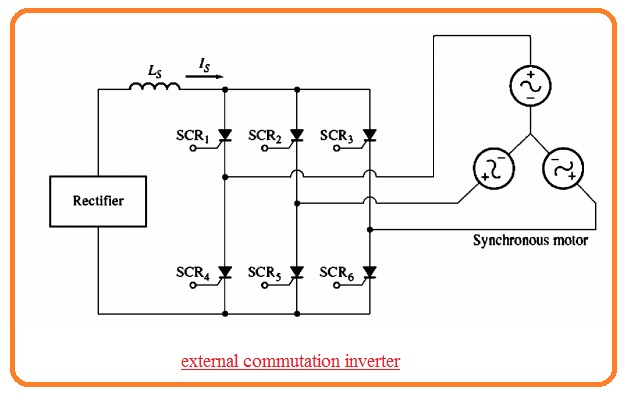
- The inverter is linked to the three-phase synchronous motor that offers the counter voltage needed to off the single SCR when other gets burnt.
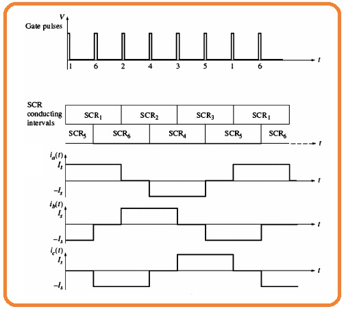
- The SCR used in this circuitry gets triggered in this sequence SCR1, SCR6, SCR2, SCR4, SCR1, SCR5.
- If the SCR1 gets to burn the interior produced voltage inthe synchronous motor offers the voltage to off the SCR3.
- Observe that if the load is not linked to the inverter the SCR will not be off and after half a cycle, the short circuitry will create through SCR1 and SCR4.
- The inverter is also known as load commutated inverter.
Self-Commutation Inverters
- It is not certain that the load will offer a certain counter voltage for commutation then the self commutation inverter will be employed.
- The self commutation inverter is a type of inverter that has active SCRs in off state through energy stored in capacitor when the other SCR is on
- It is probable to make self commutation inverter through the use of GTO or with use of power transistors in that condition commutation capacitors are not needed
- There are 3 main categories of self-commutation inverters first one is the current source the second one is the voltage source and the third one is pulse width modulation inverters.
- Current source inverters and voltage source inverts are simple than PWM inverters and are using for long time.
- PWM inverter needed further complicated circuitry and high-speed switching elements over CSI and VSI.
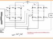
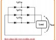
- Current source inverters and voltage source inverts can seen in below figure.
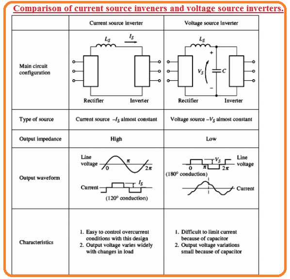
- In case of the current source inverter, the rectify is linked with the inverter through the large series inductors Ls.
- The inductance Ls has high value over the direct current is restricted to a constant value
- The SCR current output signal is a square signal because the current passing is restricted to has a constant value.
- The line-to-line voltage will has a triangular shape it is comfortable to restrict overcurrent requirements in this configuration with that output voltage can move in a result to vary the load.
- In the voltage source inverter, the rectifier is linked with the inverter from the series inductor LS and the parallel capacitor C.
- The capacitance of C is so high that the voltage is restricted to be a constant value..
- The SCR line-to-line voltage output signal will have a square shape because the voltage VC has a constant value.
- The output current will be triangular shape voltage changes are less in this configuration, the current can change according to load change and overcurrent protection is not easy to employ.
- The frequency of both current and voltage source inverter can be varied through the vary firing pulse at the gate of SCR, therefore both inverters can be employed to run ac motors at different speeds.
Read the related guide Voltage Source Inverter (VSI) : Definition, Features, Circuit
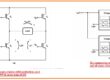
Single-Phase Current Source Inverter
- The single-phase current source inverter circuitry having capacitor commutation can seen here
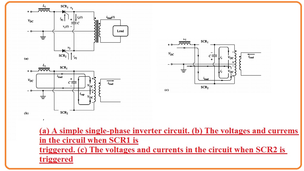
- It comprises 2 SCRs capacitors and an output transformer. For understanding the function of this circuitry suppose that 2 SCRs are off state.
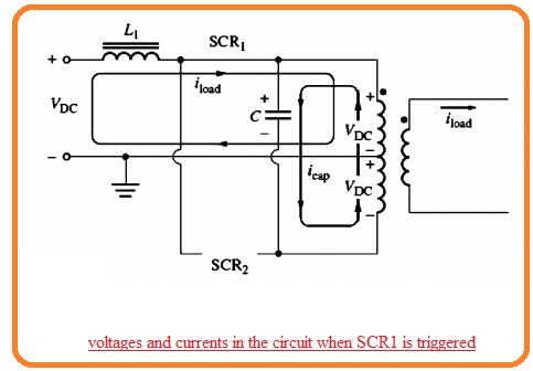
- If SCR1 is getting on through gate current-voltage VOC will be given at the upper 1/2 of the transformer in the circuitry.
- This voltage induces voltage VOC in the lowest 1/2 of the transformer resulting the voltage of 2 VOC to creates the capacitor.
- The voltage in the circuitry at this instance seen here.
- After that SCR2 gets on when SCR2 is on the voltage at cathode of SCR will have vale VDC. Because voltage about capacitor will not vary at instant basis it results the voltage at the upper portion of the capacitor to instantly vary to 3 VOC off the SCR1.
- At this point voltage at the lower 1/2 of the transformer is created to be positive at the lower to negative at upper of the windings and its value is VOC.
- The voltage at lower 1/2 induces the voltage VOC in the top 1/2 of transformer, gets to charge the capacitor to voltage 2VDC directed to the positive at lower end according to the upper part of the capacitor.
- The state of the circuitry at this instant can seen here.
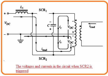
- If SCR1 burn again the capacitor voltage cut the SCR2 and this procedure continues infinitely.
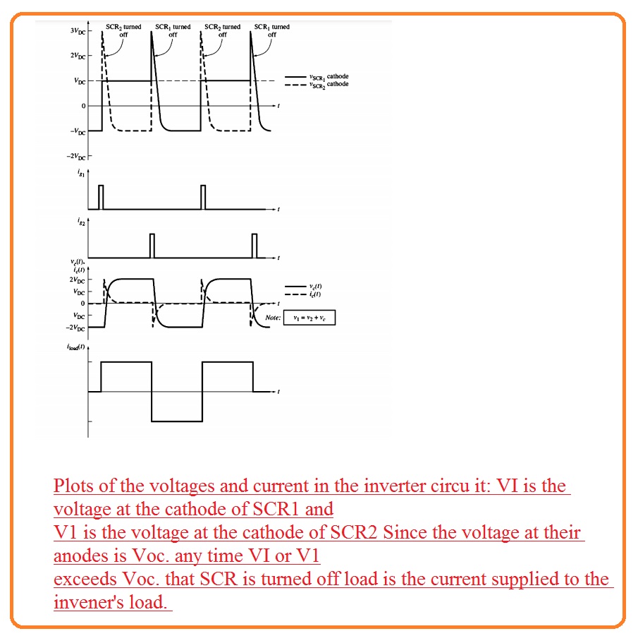
- The resultant voltage and current signal are seen here.
Three-Phase Current Source Inverter
- The diagram indicates a three-phase current source inverter.

- In this circuitry, the 6 SCRs are linked in this sequence SCR1, SCR6, SCR2, SCR4 SCR3 SCR5, and capacitors from C1 to C6 offer the commutation needed through SCR.
- To get an understanding of the function of this circuitry see the figure below
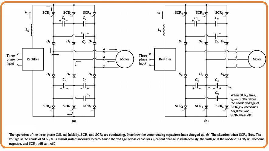
- Suppose that at start SCR1 and SCR5 are operating can see here.
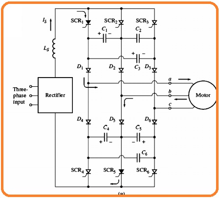
- After that a voltage will create about the capacitor C1 C3 C4 and C5can seen in figure.
- Let suppose that SCR6 is on the state.
- If SCR is getting on the voltage at the location will become zero.
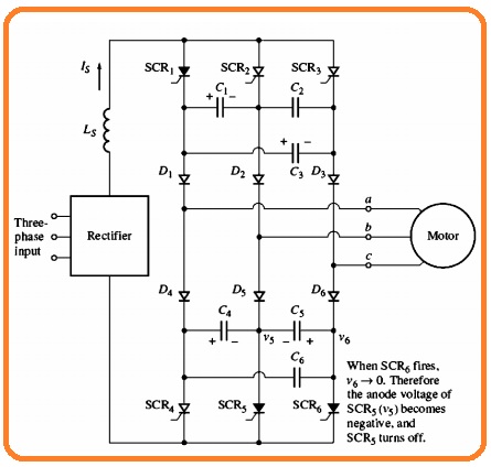
- Because the voltage about the capacitor C5 is not varied instant basis the anode of SCR is biased negatively and SCR gets off.
- When SCR is on all capacitors become charge as can see here.
- The circuitry is operating to gets off SCR6 when SCR is on.
- This similar commutation procedure provided to the top SCR bank.
- The output phase and line current through this circuitry can see here.