Hello friends, I hope all of you are doing great. In today’s tutorial, we are going to have a look at the induction motor induced-torque equation. The torque induced in any induction motor can be elaborated on as the torque produced when the electrical energy is converted into mechanical power.
The torque of the three-phase induction motor relies on the 3 very important parameters. The first one is the current induced in the rotor, the second is the stator flux that links with the rotor to produce voltage, and the third is the P.F. of the induction motor. In today’s post, we will relate all these three parameters to one another and find the induction motor torque equation by using the torque-speed characteristics and equivalent circuit of the induction motor. So let’s get started with the derivation of the induction motor induced-torque equation.
Derivation of the Induction Motor Induced-Torque Equation
- It is likely to use the corresponding circuitry of an induction motor and the power flow (flow) figure for the motor to find a universal expression for induced torque as a function of speed.
- The induced torque (tind) in the motor can be found by these two expressions.
Tind = Pconv /wm
Tind = PAG/Wsync
- The second equation is particularly valuable, as the synchronous speed (Wsync) is a constant) for a given frequency (f) and the number of poles (p).
- As the (Sync) has a constant value so we can find the induced torque (tind) of the motor by the air-gap power (PAG).
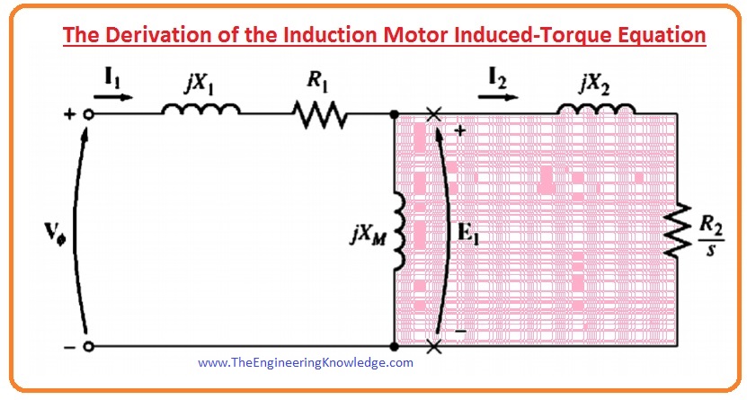
- The air-gap power (PAG) is the power crossing the (gap) from the stator circuitry to the rotor circuitry. It is equivalent to the power consumed in the resistor R2/s.
- Refer to the equivalent circuit of the induction motor, which is shown in the given diagram.
- In this picture, the air-gap power (PAG) provided to the single-ø of the motor can be given by this equation.
(PAG) 1ø = I22 (R2/s)
- So, the power gap for three-phase or total will be.
(PAG) = 3I22 (R2/s)
- If we find the value of I2 then we can easily find the value of power air gap (PAG) and induced torque (tind).
Thevenin Theorem to find the Induced Torque of Induction Motor
- Though there are numerous methods to resolve the given equivalent circuit of the induction motor for the current (l2), maybe the calmest one is to determine the Thevenin equivalent of the part of the circuitry to the left side of the (X’s) in the diagram.
- Thevenin’s theorem explains that any rectilinear (linear) circuitry that can be parted by 2 terminals from the rest of the circuitry can be replaced by a voltage source (V) in series with a corresponding impedance (Z).
- If this theorem is applied to the equivalent circuitry of induction motor, the subsequent circuit would be a simple series connection of components as shown in the picture.
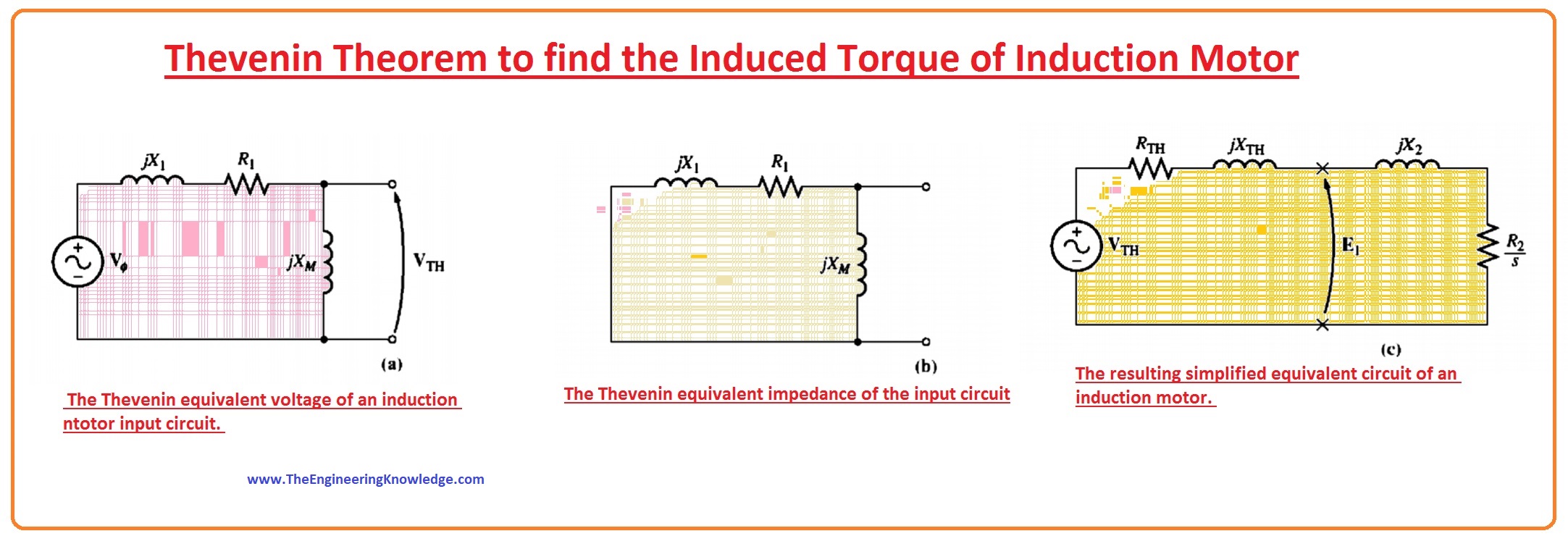
- To compute the Thevenin equivalent of the input part of the induction motor corresponding circuitry, first open-circuit the points at the (X’s) and calculate the resultant open-circuit voltage (V) existing there.
- To measure the Thevenin impedance (Z), short-circuit the phase voltage (V) and calculate the (Zeq) seeing into the terminals.
- In the given diagram (A) label circuit shows the open terminals used to calculate the Thevenin voltage (VTH). By using the voltage divider rule we get.
(VTH)= Vø(ZM /ZM +Z1)
= Vø(jXM /R1+JX1+jXM)
- The magnitude of the Thevenin voltage (VTH) is given as.
(VTH)= Vø(XM / √(R21+(X1+XM)2)
- As the magnetization reactance XM >> X1 and XM >> R1, the magnitude of the Thevenin voltage (VTH) is about.
VTH = Vø(XM /XM +X1)
- The circuit which is labeled as (B) diagram, shows that the input circuitry is short-circuited by the input voltage source. The impedance (Z) in parallel assembly and the Thevenin impedance (ZTH)is denoted as.
ZTH = (Z1ZM)/ (Z1+ZM )
ZTH = RTH + JXTH = jXM(R1+jX1)/(R1+j(X1+ XM))
- As the XM >> X1 and XM + X1 >> R1 the Thevenin resistance(RTH) and reactance (XTH) are about given as.
RTH=R1 (XM/X1+ XM )2
XTH = X1
- The subsequent corresponding circuitry is labeled in diagram as (C).
- From this circuitry, the current (12) is given as.
I2= (VTH/ZTH+Z2)
(VTH/ZTH+R2/s+jXTH+jX2)
- The magnitude of this current(I2) is given as.
I2 = VTH/√(RTH+R2/s)2+ (XTH+X2)2
- The air-gap power (PAG) is therefore given by.
PAG = 3I22(R2/s)
= (3VTHR2/s)/[(RTH+R2/s)2+(XTH+X2)2]
- The induced torque (tind) is given as.
Tind = PAG/Wsync
Tind= (3VTHR2/s)/ Wsync[(RTH+R2/s)2+(XTH+X2)2]
Comments on the Induction Motor Torque-Speed Curve
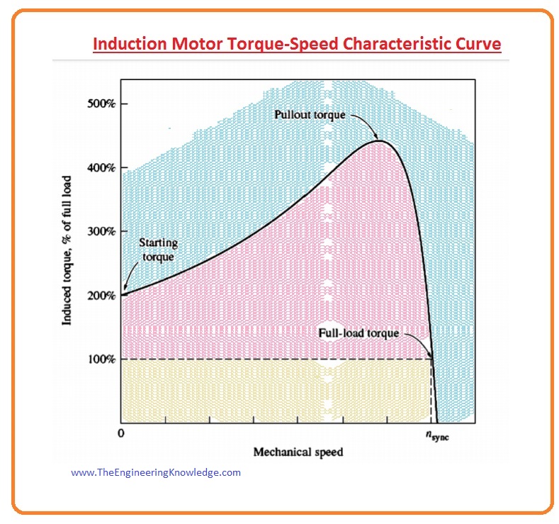
- There are two diagrams given below the first one is the induction motor torque-speed characteristic curve while other diagram offers numerous significant info about the process of induction motors. Now we discuss this information.
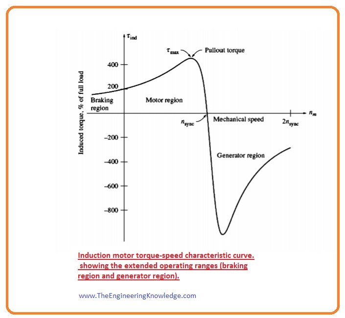
The induced torque (Tind) of the motor is 0 at synchronous speed (Wsync).
The torque-speed graph is almost rectilinear (linear) between zero load and full load conditions. In this range, the rotor resistor (RR) is larger than the reactance of the rotor (XR), so the rotor current (IR), the rotor field (BR), and the induced torque (Tind) upsurge linearly with the increment in the slip.
There is an extremely probable torque that cannot be surpassed. This torque (t) is known as the pullout torque, which is two to three times the rated full-load torque of the motor. We also have discussed the pullout torque of the induction motor.
The initial torque on the motor is somewhat greater than its pullout torque (full-load torque), thus the motor will start taking any load that it can supply at full power.
Note that the torque on the motor for a specified slip (S) fluctuates as the square of the provided voltage (V).
If the rotor of the induction motor is moving faster than synchronous speed (Wsync), then the movement of the induced torque (Tind) in the motor reverses, and the motor behaves like a generator, changing mechanical power to electrical power
- If the motor is rotating regressive comparative to the path of the magnetic fields, the induced torque (tind) will halt the motor very quickly and will attempt to move it on the other track.
- Meanwhile, changing the way of the magnetic field (B) revolution is merely a matter of swapping any 2 stator phases; this detail can be used as a method to very quickly halt an induction motor. The changing of the 2 phases for stopping the motor very quickly is called plugging.
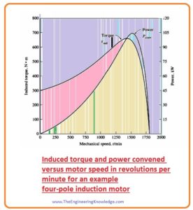
- The power converted (Pconv) to mechanical in an induction motor is given as.
Pconv = Tind x Wsync
- It is shown in the given diagram; note that the highest power provided by the induction motor exists at a different speed than the maximum torque (Tmax) and, of course, no power is transformed to mechanical power when the speed of the rotor is 0.
It is the complete and detailed article on the Induction Motor Induced-Torque Equation if you have any queries, ask in the comments. See you in the next tutorial, Maximum (Pullout) Torque in an Induction Motor.
You can also read some related articles to the induction motor. That is described here.
- Introduction to Induction Motor
- Introduction to Three Phase Induction Motor
- Equivalent Circuit Induction Motor
- Induction Motor Torque-Speed Characteristics
- Variations in Induction Motor Torque-Speed Characteristics
- Power and Torque in Induction Motors
- Induction Motor Design Classes
- speed Control Method of Induction Motors
- Induction Motor Design
- No-load Test of Induction Motor
- Solid State Drive Induction Motor
- Derivation of the Induction Motor Induced-Torque Equation