Hello, fellows. I hope all of you are having fun in your life. In today’s tutorial, we will discuss power and torque in induction motors. As induction motors are self-starting motors, their power (P) and torque (t) relations are significantly different from the relationships in the synchronous motor. As we discussed, an induction motor is also known as a revolving transformer. Its input supply is a 3-ø scheme of current (I) and voltage (V).
In the case of a normal transformer, the output is electrical power gained from the secondary part of the transformer. But in the case of the motor’s secondary part (windings) or rotor, it’s short-circuited at its end point, so it’s not possible to get output in the shape of electrical power, but its output is mechanical power. In today’s post, we will have a look at how torque is induced in the induction motor and its relationship with the power of the motor. So let’s get started with power and torque in induction motors.
Power and Torque in Induction Motors
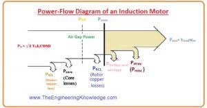
The input supply (pin) provided to the induction motor is in the form of 3-ø currents (I) and voltages (V).
After supplying input to the stator of the motor, we have to face some losses in power at the stator, which are known as copper losses or I²R losses.
Some parts of input power are also lost in the shape of hysteresis loss and eddy current in the stator part of the motor.
The residual power will have been transported to the rotor of the motor crossing the air gap between the stationary part (stator) and a rotating portion (rotor).
This power is named as the air-gap power (PAG) of the motor.
The remaining power, which is transported to the rotor after removal of copper losses I²R, is converted to the mechanical power at the rotor.
After this power loss due to friction, windage loss (PF&W), and stray losses (Pmisc), the remaining power we get at the output is called the output power of the motor (Pout).
In the power flow diagram at that point, core losses are mentioned; normally, they are not mentioned at that point.
The features of core losses, where they are noted in the motor, are slightly random.
These losses (core losses) of the motor exist half at the stator part and half at the rotor side.
Meanwhile, an induction motor generally works at a speed nearly synchronous speed (nsync), the comparative rotation of the fields above the rotor casing is rather sluggish, and the rotor core losses are small and associated with the core losses at the starting part of the rotor.
As the main portion of the core losses (I²R) is obtained from the stating part of the motor, due to this cause, core losses are pointed at that location in the power diagram.
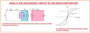
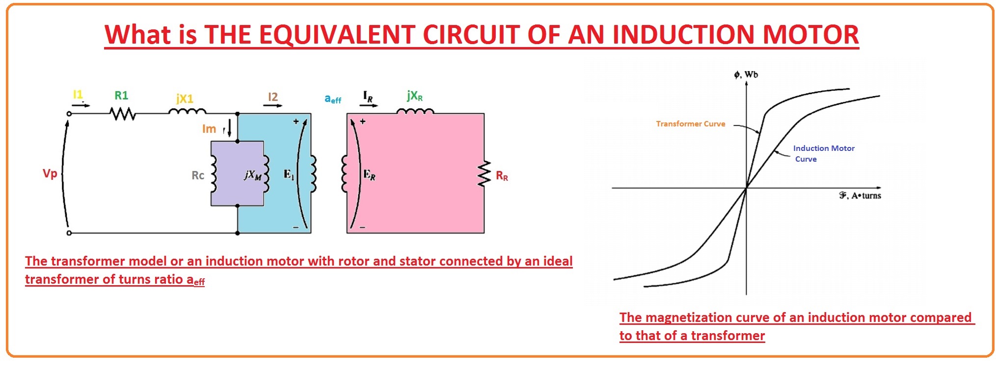
This type of loss was denoted by Rc in the corresponding (equivalent) circuit of the motor; this circuit we have already studied in the last tutorial about the induction motor equivalent circuit.
If core losses (I²R) are only assumed by a no (X watt) in its place as a circuitry component, they are frequently taken with the mechanical losses and deducted at the location on the figure where the mechanical losses are situated.
The other losses, which are stray, windage, and friction, depend on the speed of the motor; the greater the speed, the greater these losses.
But if the motor speed is almost equal to or approaches the synchronous speed, then core losses will have less value.
So, these 3 classes of losses are occasionally taken together and named as rotational losses.
The total rotating losses of a motor are frequently measured to be continuous (constant) with altering the speed, while the constituent losses alter in conflicting directions with an alteration in speed.
Power and Torque Equations of Induction Motor
First, we discuss the power equations of the rotor.
Power Equation of Induction Motor
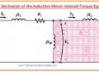
If we study the per-phase equivalent circuit of an induction motor, then we can use it to find the torque and power calculations to understand the operation of the motor.
The value of input current (I) to a phase (ø) of the motor can be created by dividing the entire input voltage (V) by the equal impedance (Z).
I1 = Vø /Zeq
Zeq = R1+Jx1 + 1/ (Gc -JBM + (1/(V2/s + Jx2) )
- So, the stator (I2R) copper losses (PSCL), the core losses, and the rotor (I2R) copper losses can be calculated.
- The stator losses (I2R) in the 3-ø are specified below.
(PSCL)= 3I1R1
- The core losses are defined as.
Pcore = 3E2 Gc
- The air gap is denoted as.
PAG = Pin – (PSCL)- Pcore
- If we observe at the corresponding (equivalent) circuitry of the rotor. The component in the circuitry where the air-gap (PAG) power can be spent is in the resistance R2/S.
- So, the air-gap power (PAG) can also be given as.
(PAG) = 3I22 (R2/s) ——(A)
- The real resistive power losses in the rotor circuitry are assumed by the equation.
PRCL = 3I2 R x RR
- As the power is unaffected when referred) to a perfect (ideal) transformer, the rotor copper losses (PRCL) can also be stated as
PRCL =3I2 2 x R2 —(B)
- When all losses that exit in a motor like PSCL , core losses, and copper losses at rotor, are eliminated from the input supplied to power, the residual power is transformed from electrical to mechanical power.
- This converted power can be defined as.
PCONV = PAG-PRCL = (3I2 2 x R2 /s) – (3I2 2 x RR) = 3I2 2 R2 (1/s – 1)
- From equations A and B, we can see that the rotor copper losses (PRCL) are equivalent to the air-gap power (PAG) multiplied by the slip (S).
PRCL = sPAG
- From this equation, we can see that rotor copper losses are directly proportional to the slip of the motor.
- If the rotor is not moving then the slip value will be one, then the PAG is completely spent in the rotor.
- It is reasonable if the rotor is not moving the Pout will be 0.
- As we discussed earlier.
PCONV = PAG-PRCL
- It will provide additional association among the air-gap power (PAG) and the Pconv from electrical to mechanical.
PCONV = PAG-PRCL
- Putting the value of PRCL in the above equation.
PCONV = PAG– sPAG
PCONV = (1-s)PAG
- If we know the value of friction, stray and windage losses, then the desired output power of the motor can be defined as.
Pout = Pconv– PF&W – Pmisc
- Pout is the output power of the motor which we obtain after the removal of different losses that exit in the three-phase induction motor.
Torque in Induction Motor
- Induced torque Tind in a motor is explained as the torque produced by the internal electrical-to-mechanical power transformations.
- This torque (t) varies from the torque actually obtainable at the points (terminals) of the motor by a quantity identical to the friction and windage torques in the motor.
- The value of torque is defined as.
tind = Pconv /wm
- This torque is known as the induced torque in the motor.
- The above-given equation of torque can also be defined in terms of slip and power air gap losses.
tind = (1-s)PAG / (1-s)wsync
- This equation is particularly very valuable as It explains the induced torque (tind) in the form of air-gap power (PAG) and synchronous speed (Wsync), which does not fluctuate. Information of (PAG) consequently directly affects tind.
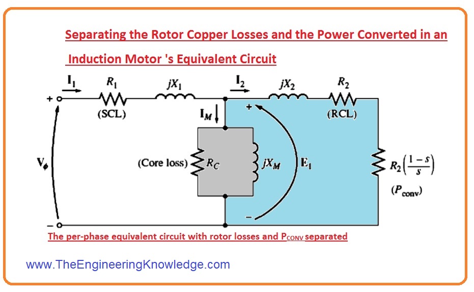
Separation of PRCL and Pconv in Equivalent Circuit of Induction Motor
- As we have discussed that the power coming from the (PAG) some is lost in the rotor copper (PRCL) and the remaining is converted into the mechanical power output.
- It is likely to distinguish the 2 parts of the air-gap power (PAG) and to designate them distinctly on the motor circuitry.
(PAG) = 3I22 (R2/s)
PRCL = 3I2 R x RR
- These 2 given equations provide expressions for air-gap power losses and rotor copper loss.
- The air-gap power (PAG) is the power that will be spent in the resistance of value R2/s.
- Whereas the rotor copper loss (PRCL) is the power that will be spent in resistance of value R).
- The alteration among them is (Pconv), which should be the power spent in the form of resistance.
Rconv = (R2/S) – R2 = R2(1/s -1)
- Per-ø corresponding circuitry with the rotor copper losses (PRCL) and the power transformed to mechanical, parted into separate components, is revealed in the diagram.
Read also:
What is the relationship between power and torque in induction motors?
The relation between torque and power is directly proportional. The power of rotating objects can be a scalar product of torque and angular velocity.
What is the torque in an induction motor?
Torque is the turning force through a radius, with units of Nm in the SI system and units of lb-ft in the imperial system. The torque produced with an asynchronous induction motor changes if the motor accelerates from 0 to the highest operating speed.
What is the difference between torque and power in electric motors?
Torque is force generated through the burning of hydrocarbon fuel in the engine or through applying current to the motor. Power is the torque product with engine speed.
Why does torque increase with RPM?
The torque RPM curve starts with a vast increase in torque as RPM increases from zero. It means that as engine speed increases from a standstill, it also produces more rotational force, helping the vehicle’s acceleration.
What is the principle of an induction motor?
The motor that operates on electromagnetic induction is called an induction motor. Electromagnetic induction is a phenomenon where emf is induced over an electrical conductor when it is put in a rotating magnetic field.
Why is starting torque high in an induction motor?
A slip ring induction motor comes with starting torque since the slip ring is connected through resistance. If the supply is on, the resistance increases; the phase difference reduces due to the starting torque increase.
It is the complete article on the power and torque of induction motors, I have described the equation and related terms of the power and torque. If you have any questions, ask it in the comments. See you in the next tutorial Induction Motor Torque-Speed Characteristics.
You can also read some related articles on the induction motor. That is described here.
- Introduction to Induction Motor
- Introduction to Three Phase Induction Motor
- Equivalent Circuit Induction Motor
- Induction Motor Torque-Speed Characteristics
- Variations in Induction Motor Torque-Speed Characteristics
- Power and Torque in Induction Motors
- Induction Motor Design
- Induction Motor Classes Design