 Hello friends, I hope you all are doing great. In today’s tutorial, we will have a look at How to Troubleshoot FET Circuits. The FET stands for the field-effect transistor is a category of transistor that control current through the electrical field. Like BJT this transistor also has three terminals which are gate, drain, and source. This electronic component regulates the movement of current with the use of voltage at the gate terminal, that in results changes the conductivity among the drain and source.
There are two main types of FET first one is JFET (junction field-effect transistor) and second one is MOSFET (metal oxide field effect transistor). MOSFET is further divided into two types E-MOSFET and D-MOSFET which we have described with the detailed in previous tutorial. It today’s post we will have a detailed look at its troubleshooting and related parameters. So let’s get started with How to Troubleshoot FET Circuits.
Error in Self-Biased JFET Circuits
First Symptom: VD=VDD
- In this situation the value of drain current should be zero since voltage loss about is zero.It is shown in figure denoted as ‘a’.
- For any circuitry, it is good troubleshooting technique to find open or loss connection also burnt resistances.
- After that remove power supply and calculate suspected resistance for open circuitry.
- It these are good then there will be some issue with the
- The given below errors can cause this symptom.
- There is no ground terminal at resistance Rs.
- Resistance Rs is open.
- The connection of drain lead is open.
- The connection of source lead is open.
- FET is interiorly open among the drain and source.
2nd Symptom : VD Less Than Normal value
- For this state, if the supply voltage is lesser than it must be, the drain current should be greater than normal value since voltage loss about resistance RD is large.
- The figure denoted as ‘b’ explained this condition.
- These below given errors can cause this symptom.
- Resistance RG is open
- The lead of gate is open
- FET is interiorly open at gate.
- Any fault of these 3 will eliminate the depletion region from the JFET so drain current is restricted only by resistance RD, RS and less value channel resistances.
Error in D-MOSFET and E-MOSFET Circuits
- The main fault which is difficult to find is open gate in a zero bias D-MOSFET.
- For zero biased D-MOSFET gate to source voltage are zero in ideal case when open circuit exist in gate circuitry.
- So drain current does not vary and the bias look in normal state as shown in below figure.
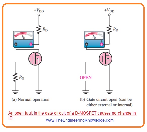
- Though, static charge as a consequence of the open can causes drain current to act irratically
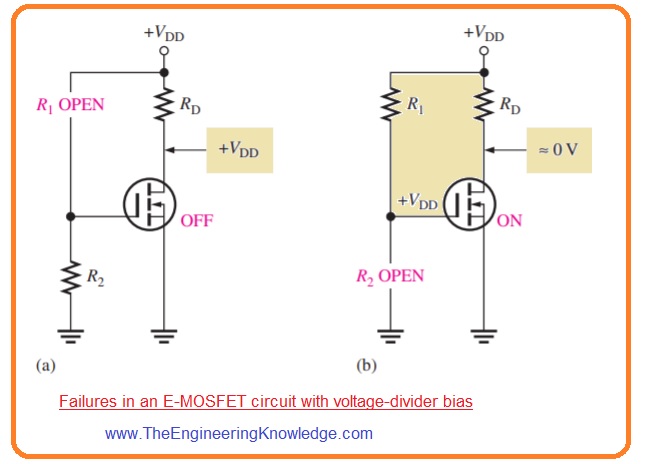
- In E-MOSFET circuitry with the voltage divider bias configuration an open resistance R1 causes voltage of gate to zero.
- Due to that transistor is off and behave like an open switch circuit since gate to source threshold voltage larger than the 0 is needed to on the transistor.
- This situation is explained in figure denoted as ‘a’. If resistance R2 is open the gate voltage is +VDD and channel resistance is very less transistor or device operates like closed switch.
- The drain current is restricted through resistance RD this condition is explained in figure denoted as ‘b’.
What is the working principle of FET?
- A field-effect transistor is a component that operates on field-effect features. The field effect defines the modulation process of longitudinal current flow between two pins of devices with a transverse electric field given to the 3rd terminal.
How do I check if my MOSFET is faulty?
- Set the meter diode modem; after that, make the connection of the red pin of the digital meter with the drain pin and the black pin with the source terminal. If there is no continuity between these two pins, the MOSFET is working well. There is not enough gate source voltage needed to provide for turning on the MOSFET.
How do you check if a multimeter is working correctly?
- Use probes with each other for testing the meter is working well. If probes are clicked with each other, the display will show a reading of 0.00 or a short circuit. If we move the probes, it separates and reads 1 or OL, which is an open loop or short circuit.
How to troubleshoot a circuit with a multimeter?
- Put a black pin at the ground point. Red pin connect and check voltage reading at each testing point for starting at testing point 1. Make sure power supply. Regularly work through the circuit until you get a 0 result that shows a break in the circuit before that point.
Read also
So that is detailed post about Troubleshoot FET circuits if you have any question ask in comments. Thanks for reading. Have a good day.