Hello, fellows, I hope all of you are having fun in your life. In today’s tutorial, we will discuss the lap winding in DC machines. The rotating part, which is the rotor of any DC machine, whether it is a motor or DC generator, has a very important part of the machine that is the armature of rotor windings. The electrical power is transformed, in the case of a motor, into mechanical power, and mechanical power into electrical in the case of a generator at this part of the machine. There are two main types of rotor windings. The first one is lap winding, and the second one is wave winding, but there are subcategories of armature windings that are also used, like simple, duplex, multiple, etc.
In today’s post, we will have a detailed look at lap windings, their construction, and their connection with the commutator. So let’s get started with the lap windings in DC machines.
Lap Winding in DC Machines
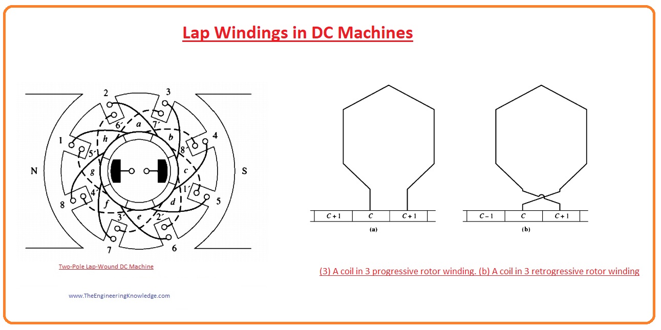
Lap windings are a very simple and normally used winding in DC machine rotors. Simplex lap windings have two end points and more than one number of turns, and their endpoints are connected with neighboring commutator segments.
If one end of these windings is connected with one commutator segment and the second end of the windings with other neighboring commutators, it means if the first end is linked with ‘n’ commutators and the second will be connected with ‘n+1,’ this type of winding arrangement is known as progressive winding, and the commutator pitch will be ‘1’ and denoted as yc.
If the first end of the winding is linked with one commutator segment and the other ends with the previous segment, in simple words, one end is connected with an ‘n’ segment and the other with an ‘n-1’ segment, then this type of winding arrangement is known as retrogressive lap winding. The value of the commutator pitch is ‘-1.’
The 2-pole DC machine having lap winding is shown in this given figure.
- The machine having lap winding has parallel paths for a current equivalent to the no of poles in the device.
- If we denote both no of windings and commutators by ‘C’ and ‘P’ are no of poles, then the no of coils in every current path can be found by the ‘C/P’ formula.
- For a practical understanding of this formula lets discuss this given below figure that has a motor with 4 no of poles.
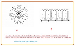
You can see that there are 4 current paths available, and the voltage through these paths is equal due to the parallel combination.
The point is that numerous current pathways exist in multiple pole machines that make lap winding the best option. Less voltage and large current machines, and high current do not affect the working of machines having lap windings due to distribution in more than one path.
This current distribution retains the size of the rotor conductor within certain limits if the current has a large value.
Problems of Lap Winding in DC Machines
With the advantage of lap windings in DC machines, there are some drawbacks of lap windings.
For observation of these disadvantages, let’s see this given below figure. That has a machine with 6 poles.
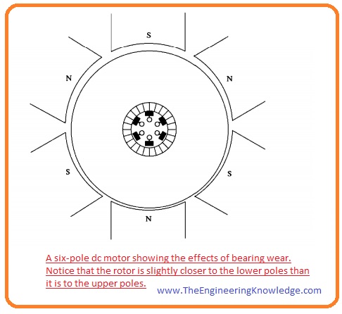
Since extensive operation, there is minor wear on the bearings, and the lower conductors of the windings are near the poles while the upper conductors are at some distance.
As a consequence, there is a higher value of voltage in the current paths having conductors lower the poles, while current paths having upper conductors have less value of voltage.
As all current paths are linked with one another in parallel fashion, some parts of the total current come out at the output while some move back in other parts of the machine; you can see this in a given figure. 8-17
It is not perfect for a machine, as the value of resistance at the rotor’s windings has less value; there is a little bit of variation in the value of the voltage at parallel paths that causes a huge current to flow through the brushes, that generate a huge amount of heating.
How to solve problems of lap windings
The issue occurring due to the circulation of current in the parallel paths of any DC machine having 4 or more poles cannot be completely reduced but can be minimized to some extent.
To minimize these problems, special windings are used, known as
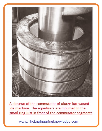
These equalizers are bars placed on the rotor of a machine having lap windings and connected with each other at a similar voltage level at current parallel paths.
These connections (shorting) of bars allow current to pass through these equalizers instead of brushes of the machines.
These circulations of current resolve partly the flux misbalancing that affected them to exist in the first place.
An equalizer connected with the machine having 4 poles is shown in the given figure.
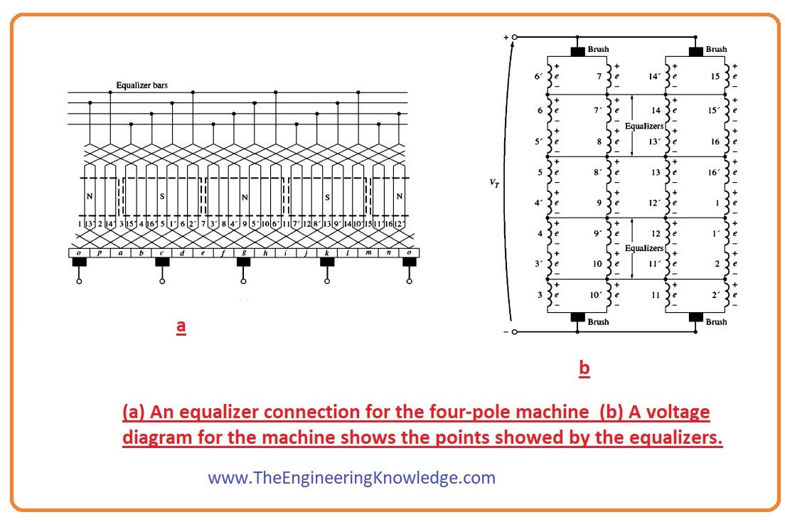
- An equalizer for a large lap dc machine is shown in Figure.
If we wound a duplex lap winding on a DC machine, then there will be 2 complete windings that will be wound on the rotor; each commutator segment will be linked with the single winding.
So, a discrete coil ends on the 2nd commutator down from where it is ongoing, and Yc=+-2.
As we discussed earlier, every set of windings in lap windings has no parallel paths equal to poles in a machine, so in a duplex lap winding the current paths will be twice.
In simple words for n-plex lap windings, the value of commutator pitch Yc is given as.
Yc=+-n lap windings
- The no of current paths will be.
- a=np
- In this equation.
- a is no of current paths.
- n is plex of windings
- P is no poles.
So that is the detailed post on the Lap Winding in DC Machines if you have any questions about this post ask in comments. Thanks for reading. See you in the next tutorial.