
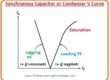
Hello friends, I hope all of you are having fun in your life. In today’s tutorial, we are going to have a look at synchronous motor power correction. A synchronous motor is such a machine that can operate at unity, lagging, and leading P.F., but an induction motor operates only on lagging P.F. The synchronous motor P.F. varies with a variation in field current. If it increases the value of P.F., it shifts from lagging (inductive) to unity and then becomes capacitive (leading). This feature of the motor works with different PFs used in the power system to improve the PF.
When the motor operates for power factor correction, then there is no load connected with it. It excites in such a way that it increases the power factor of the system, meaning it makes it lead. In this case, this motor is recognized as a synchronous condenser. In industries, the induction motor is generally used. When an induction motor is connected with a full load, it has a 0.8 lagging P.F. Due to variation of loads, the value of P.F. of this motor decreases to 0.6 lagging, but this is not good for appliances connected with the motor to operate at such a low P.F. For the improvement of the P.F., a synchronous motor (condenser) is connected in parallel with an induction motor for power factor improvement. In today’s post, we will discuss how a synchronous motor is installed in a system for power factor improvement. So let’s get started with Synchronous Motor Power Correction.
Synchronous Motor Power Correction
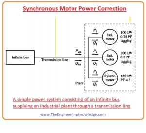
- In the given figure, you can see that the output of the infinity bus bar (large power system) is connected with the industrial load by the transmission line.
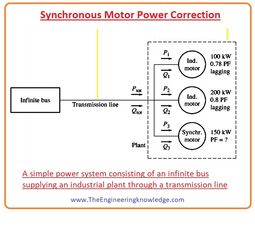
There are 3 loads connected with it; the first 2 are induction motors having lagging P.F., and the 3rd is a synchronous motor that has unity, lagging, and leading P.F.
For understanding the P.F. variation and effects of these three loads, we solve a numerical problem. Whose statement is written here.
In the above figure, you can see that an infinite bus bar (large power system) is operating at four-eighty (480) volts. The first induction motor connected with this system consumes two hundred kilowatts (200 kW) at a 0.78 lagging power factor; the second induction motor uses two hundred kilowatts (200 kW) at a 0.80 lagging power factor. The synchronous motor uses 150-kilowatt real power, so we have to find these three conditions.
If a synchronous motor operates at a 0.85 lagging power factor, then what is the value of the transmission line?
If a synchronous motor operates at a 0.85 leading power factor, then what will be the value of the current?
If the power loss of the transmission line is given.
PLL =3I2LRL
- What will be effect of these losses on first two conditions?
Solution
- You can see in the above-given figure that the active power of first induction motor is a hundred kilowatts (100kw) and its reactive power Q is given as.
Q1=P1tanø
=(100kw)tan (cos-178)
=(100kw)tan38.70
=80.2KVAR
- The value of active power of the second induction motor is two hundred kilowatts (200kw) so its reactive power will be.
Q2=P2tanø
=(200kw)tan (cos-180)
=(200kw)tan36.870
=150KVAR
- The synchronous motor’s active power is one-fifty (150) so its reactive power will be.
Q3=P3tanø
=(150kw)tan (cos-185)
=93kVAR
- If we add active powers of these three loads than we have.
Ptot= P1 + P2 +P3
=100kw +200kw+150kw
=450kw
- So total reactive power will be.
Qtot = Q1 + Q2 +Q3
Qtot=80.2KVAR +150KVAR + 93kVAR
=323.2KVAR
- The corresponding system power factor is given as.
F =cosø= cos (tan-1(Q/P))
= cos (tan-1(2KVAR/450kw))
=cos35.70= 0.812 lagging
- So the line current will be.
IL=Ptot/VLcosø
=(450 kW)/(480V)(0.812)
=667 ampers
- b). The active and reactive powers (Q) of the induction motor are constants while the synchronous motor’s power is varying. So the reactive power of the synchronous motor will be given as.
Q3 = P3tan(ø)
=(150 kW) tan (-cos-l85)
=(150 kW) tan (-31.8°)
=-93KVAR
- So total real power will be.
Ptot = P1 + P2 + P3
= 100 kW + 200 kW + 150 kW
= 450kW
- And total reactive power is.
Qtot= Q1+Q2+ Q3
= 80.2 kVAR + 150 kVAR – 93 kVAR
=137.2 kVAR
- The corresponding system power factor is.
F =cosø= cos (tan-1(Q/P))
= cos (tan-1(2KVAR/450kw))
=cos16.60= 0.957 lagging
- So transmission line losses is.
IL=Ptot/VLcosø
=(450 kW)/(480V)(0.957)
=566 ampers
- C). so line losses in the first case are given as.
PLL=3I2LRL
=3(376A)2 RL
=1344700RL
- In the second case line losses will be.
PLL=3I2LRL
=3(566A)2 RL
=961070RL
You can see that power loss in the second case is 28% less than in the first case, but the power is similar in these 2 cases.
You can observe from this example problem that adjusting the P.F. of loads in the system also disturbs the efficiency of the system.
The decrement in P.F. causes an increment in losses of line delivering power to the loads.
In industries, mostly loads are induction motors, so the P.F. of the system will be lagging.
The existence of a synchronous motor system provides some benefits to a system that are described here.
Synchronous Motor Importance for Industries
If there is such a load industry, like a synchronous motor that has a leading P.F., it can provide Q to an adjacent lagging P.F. load instead of using a separate generator used for reactive power.
Due to easy access to reactive power for lagging power industries by synchronous motors, it decreases power losses that will occur if we get reactive power from some distant generator. As this power has to come by transmission line due to its resistance, some power loss will occur in traveling to the load. Like we discussed in the above-given example.
As the transmission lines transmit a lesser amount of current, they can be reduced for a given rated power movement. A lower apparatus current rating decreases the price of a power system meaningfully.
• If a synchronous motor is used in a system to improve P.F., then it should be in an over-excited condition. It will enhance the extreme (maximum) torque and decrease the possibility of unintentionally surpassing the pullout torque.
The implementation of synchronous motors or any other device for the improvement of the power factor of a system is known as power-factor correction.
As a synchronous motor can deliver an improvement of P.F. and decrease the price of a system, numerous loads that can take a constant-speed motor are operated by synchronous motors.
Though the price of a synchronous motor is is higher than an induction motor due to its complex circuit and separate field excitation, its power factor improvement ability makes it effective for industries because it saves an amount that is used due to a lagging power factor.
Precaution for Synchronous Motor USE
- The synchronous motor used in industries for power factor improvements and high pullout torque has to operate in over-excited conditions.
- For this, overexcitation there is a need of a large amount of field current that also generates heat in the motor’s rotor.
- So during overexcitation, we should set the field current at a value that cannot produce heating in the machine.
- I have also written some related articles; you can also read them, which are listed here.
- Introduction to Synchronous Motor
- Synchronous Moor Torque-Speed Characteristic Curve
- Synchronous Motor Starting Method
- What is Synchronous Condenser (Capacitor)
- Synchronous Motor Power Correction.
- Types of Synchronous Motor
- Effect of Field Current Changes on a Synchronous Motor.
It this complete post on Synchronous Motor Power Correction, I have mentioned each and everything related to this topic. If you have any questions about it ask in the comments. See you in the next tutorial: synchronous condensor.


There is definately a great deal to learn about this topic.
I like all the points you’ve made.