A flasher relay is an electrical component that produces blinking for signal and hazard lighting. If signal failure occurs when switching LED bulbs, replacing the thermal relay with an LED-supported flasher relay is the fastest and best solution. In this post, we will detail the features of a flasher relay and its importance in circuits
What is a Flasher Relay
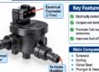
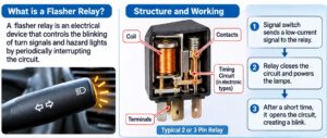
A flasher relay is an electromechanical device used in vehicle lighting systems that regulates the flashing of turn signals and hazard lights. This relay periodically interrupts current to provide the standard flashing pattern for easy communication. For the timed switching process, it provides a constant flash rate that meets safety standards.
The relay is part of this system and works as a building block of the circuit. through activating the driver on the signal lever and gives a low-current signal to the relay electromagnet. The magnet closes the high-current connection to give power to bulbs. That provides protection to switch from high amperage.
A flasher works as a thermal switch that, in older circuits, is used as a bimetallic strip bent when heated by current, breaking the circuit and turning on the light. But new units have full electronic features with internal timing chips for constant flashing of the bulb load without considering the heat produced by the bulb.
Types of Flasher Relays
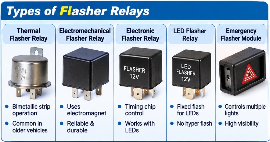
Flasher relays come in different types since flasher technology is growing from thermal units to solid-state devices.
LED Flasher Relay Bike
- The bike comes with compact 2-pin relays. Older models of motorbikes currently use a bimetallic strip, causing deformation and circuit breakage. When the LED has less current, about 0.5 amperes, no high heat is produced that can bend the strip, and the blink cycle starts.
New motorcycle LED flasher relays come with full electronic features, and their rating is 0.5 amperes to 10 amperes, and they have easy connection to a two-pin socket for proper flashing of other used
Electronic Flashers
Its other name is a no-load flasher, and it is for basic usage replacement of LED conversion. No low flasher is not based on the amperage draw through bulbs for finding flashing speed; that is using an inner timing chip. It comes in two main types: solid-state and relay-based. The vehicle has a CAN bus system or a digital dashboard with a basic no-load flasher that does not clearly show bulb-out. A warning message also if lights are blinking properly, and for such conditions, a CAN bus is used
Emergency Light Flasher Module
These are certain modules part of trucks and construction devices. They have different features compared to the standard turning relay in terms of managing many lights at the same time with a high-visibility structure. They have features for high-amperage loads compared to standard turn signal relays.
Flasher Relay Pin and Wiring Basics
The flasher relay comes with a compact 2-pin or 3-pin connection configuration. Some types come with a four-pin system. Their labels are as
| Pin | Function | meaning |
| B / X | Battery | Gets fused supply voltage from the vehicle system. |
| L | Lamp output | Provides flashing power to the turn switch or lamps. |
| E | Earth/ground | Used in many electronic flashers for stable operation. |
| P | Pilot indicator | Drives the instrument cluster or indicator lamp in some architectures. |
Accurate wiring with connecting of accurte pin at right point and with that.
- Relay supply gets protection with a proper fuse, and the ground path has low resistance and no corrosion.
- The steering switch is not adding contact resistance.
- lamp harness is not adding extra damage points.
Flasher Relay Producing Blink Pattern
The main function of the flasher relay is to make connections and disconnections of lamp supply. Techniques used for getting cycles define each feature.
The thermal flasher lamp current is a component of the timing system. High current results from high-speed heating; different heating causes affect timing, and varying ambient temperature varies fast, stripping low temperature.
So, flashing occurs with a combination of load thermal conditions and mechanical operations. So, burning an incandescent bulb causes different flashing features
for electronic flasher timing of oscillator, timer system. Lamp current is the basic load on output points. This decoupling offers electronic flasher management for LEDs, with low lamp current, not affecting flash timing assumptions
Comparison of Different Flasher Relay Types
| Technical features | Thermal Flasher Relay | Electromechanical Flasher Relay | Electronic Flasher Relay | LED Flasher Relay | Solid-State Flasher Relay |
| Operating voltage | 6V, 12V, 24V | 6V, 12V, 24V | 12V, 24V | 12V, 24V | 12V, 24V |
| Operating principle | Bimetallic heating | Electromagnetic switching | Electronic timing control | LED-load-compatible electronic timing | Semiconductor switching |
| current rating | 2–10A | 5–20A | 5–20A | 1–20A | 5–30A |
| Flashing frequency | Load-dependent | 60–120 flashes/min | 60–120 flashes/min | 60–120 flashes/min | 60–120 flashes/min |
| Flashing duty cycle | Load-dependent | Design-dependent | Typically 40–60% | Typically 40–60% | Design-dependent |
| Load type | Incandescent bulbs | Incandescent bulbs | Incandescent and compatible LED loads | LED and compatible incandescent loads | LED and incandescent, depending on design |
| Timing accuracy | Low | Moderate | High | High | High |
| Switching element | Bimetallic contacts | Mechanical contacts | Transistor or relay | MOSFET or transistor | MOSFET or semiconductor |
| Operating temperature | Design-dependent | Design-dependent | -40°C to +85°C | -40°C to +85°C | -40°C to +105°C |
| Voltage tolerance | Design-dependent | Design-dependent | Model-dependent | Model-dependent | Model-dependent |
| Reverse polarity protection | Generally unavailable | Generally unavailable | Model-dependent | Model-dependent | Model-dependent |
| Short-circuit protection | Limited | Limited | Model-dependent | Model-dependent | Model-dependent |
| Overload protection | Thermal response | Contact/load dependent | Model-dependent | Model-dependent | Model-dependent |
| Switching life | Limited by contact wear | Limited by mechanical wear | High | High | High |
| Audible operation | Clicking | Clicking | Usually silent | Usually silent | Silent |
| application | Older automotive systems | Conventional turn signals | Modern vehicle lighting | LED indicator systems | Advanced automotive lighting |
Flasher Relay vs Hazard Flasher Unit
| Feature | Flasher Relay | Hazard Flasher Unit |
| Definition | An electrical switching device that controls the ON/OFF operation of turn signal lights | A control unit that functions all vehicle turn signal lights simultaneously |
| function | Controls left and right turn signal flashing | Controls simultaneous flashing of all four turn signals |
| Operating purpose | Vehicle’s turning direction | Warns other road users about an emergency or stationary vehicle |
| Light operation | Activates either left or right indicator circuit | Activates both left and right indicator circuits |
| Switching mechanism | Thermal, electromechanical, electronic, or solid-state | electronic or relay-based |
| Circuit connection | Connected to the turn signal circuit | Connected to both left and right indicator circuits |
| Control input | Turn signal switch | Hazard warning switch |
| Flashing pattern | Alternating ON/OFF flashing | Both sides flash ON/OFF simultaneously |
| operating voltage | 12V or 24V DC | 12V or 24V DC |
| Load compatibility | Relay design and current rating | Hazard circuit and flasher unit rating |
| components | Timing circuit, switching contacts, or semiconductor components | Hazard switch, control circuit, flasher unit, and wiring |
| Power supply | Vehicle electrical system | Supplied through a separately protected, battery-fed circuit |
| Operating condition | During normal driving and turning | Used during emergencies, breakdowns, or warning situations |
| LED compatibility | Flasher relay type | Hazard control unit and LED load compatibility |
| applications | Cars, motorcycles, trucks, and buses | Cars, trucks, buses, trailers, and motorcycles |
| advantage | Clear directional signals | Vehicle visible as an emergency warning |
| limitation | Does not normally activate both indicator sides simultaneously | Not intended to indicate normal turning direction |
Flasher Relay vs Body Control Module (BCM)
| Feature | Flasher Relay | Body Control Module (BCM) |
| Definition | An electrical switching device that controls the flashing operation of vehicle turn signals | An electronic control unit that manages many electrical and electronic functions in a vehicle |
| function | Controls the ON/OFF timing of turn signal lights | Controls lighting, locking, wipers, windows, and other body electrical systems |
| Operating principle | Thermal, electromechanical, or electronic switching | Microcontroller-based electronic control |
| Components | Bimetallic strip, contacts, coil, timer IC, or transistors | Microcontroller, input/output circuits, drivers, memory, and communication interfaces |
| Signal processing | Basic timing and switching | Processes multiple sensor, switch, and vehicle system signals |
| Flashing control | Directly controls the turn signal flashing rate | Produces and manages turn signal timing through programmed logic |
| Turn signal operation | Controls left and right indicator circuits | Controls left and right indicators through electronic output drivers |
| Hazard light control | Supports hazard flashing when connected to the hazard circuit | Can control hazard warning lights through integrated software and output circuits |
| Operating voltage | 12V or 24V DC | 12V or 24V vehicle electrical systems |
| Output switching | Mechanical contacts or semiconductor switches | Electronic drivers, MOSFETs, or external relays |
| Communication | Usually operates independently | Can communicate through CAN, LIN, or other vehicle networks |
| Protection features | Based on relay design; may include basic overload protection | Overcurrent, short-circuit, thermal, and voltage protection |
| Diagnostic capability | Usually limited | Supports diagnostic trouble codes (DTCs) in many vehicles |
| Programmability | Fixed operating characteristics | Software-configurable functions, depending on vehicle design |
| Applications | Turn signals, hazard lights, and indicator circuits | Central locking, interior lighting, exterior lighting, wipers, windows, and security systems |
| Advantage | Simple, inexpensive, and easy to replace | Integrates and manages multiple vehicle electrical functions |
| limitation | Limited functionality and control | Complex, expensive, and requires specialized diagnostics |
Symptoms of a Bad Flashing Relay
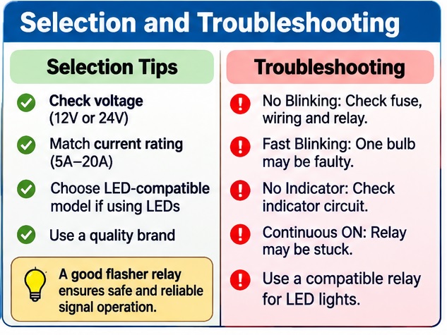
Different signs show the flashing relay is faulty.
The hazard light is not working.
If the relay is in an open condition, the circuit is not closing, and no power goes to the lights. With that, the left or right turn signal is working, and the hazard light stops working; it means the relay is faulty
Hazards Won’t Turn Off
In some conditions, the relay connection is welded or stuck in a closed condition. This causes the turn signal lights not to blink when the ignition is on,
Lights Malfunction
Electrical systems are connected to each other. A short relay causes feedback loops, causing the dashboard to glow and brake lights to turn on, with other devices having a common ground connection.
How to Troubleshoot Flasher Relay
There are different troubleshooting features for the flasher relay.
When you find hyper flashing that occurs due to load mismatching, LED retrofit, or a burned-out bulb. In these conditions, check the bulb type and current flow on both sides.
If lamps stay solid and do not flash, that occurs due to the wrong relay used, a stuck relay, or BCM logic faults. For these conditions, ensure system design and relay configuration.
If there are no lamps, the main causes are a lost fuse supply and a switching error. That means check the supply at the relay input before using the new component.
If one side of the relay works differently than the other, it is the result of socket corrosion, bulb fault, or local ground error. In these conditions, inspect the resistance of the side lamp and ground losses.
Random timing occurs due to loose connections, vibrations, unstable voltage, and ground errors. So check connectors and minor voltage during active flashing
Selection factor of Flasher Relay
Selection of a flasher relay is an important factor; before using a certain relay, you must consider these factors.
System voltage
Some vehicles come with a 12 V system, but trucks and vehicles used in industries are often 24 V. Check supply voltage; not mentioned, mostly low voltage, features when cold cranking occurs.
Load
Check lamps connected under working conditions, also trailer loads and the pilot indicator. In the case of a thermal unit, certain current exists for timing functions, not for power-handling features.
Incandescent vs LED features
It is a main feature; if LEDs exist, use them accurately. Retrofits are mostly damaged due to the relay used for connector fitting, not electrical features.
Pinout
The same PIN does not give an idea of the same mapping; check terminal function, cavity configuration, and ground reference needed
- Working conditions are also important before selecting a relay, such as vibration, dust, and trailer exposure. The environment has a high effect on timing circuits