Electrostatic discharge control at electronics workstations is based on comparing it to putting an ESD mat on a workbench. Work should come with a controlled electrical path that provides charge dissipation while maintaining an effective connection with the grounding system. In electronics projects, PCB assemblies, repairing systems, and electrostatic protected areas (EPAs), resistance testing is preferred for checking ESD working surface functioning according to requirements.
This tutorial will cover how resistance-to-ground and point-to-point measurements can be used to evaluate an ESD work surface, what equipment is required, and which common testing errors can produce misleading results.
ESD Work Surface Resistance Importance
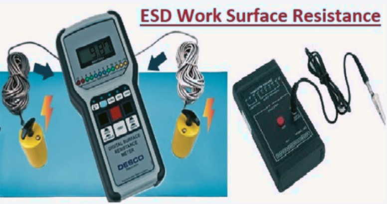
An ESD work surface helps control electrostatic charge over electrostatic discharge sensitive (ESDS) devices.
A basic two-layer rubber ESD mat comes with:
- a static-dissipative working surface;
- a more conductive lower layer;
- a grounding connection;
- a ground cord connected to an approved grounding point.
If accurately connected, that design offers a controlled path from the working surface toward ground.
However, the electrical features of a working surface can change.
Main causes are
- surface contamination;
- dust accumulation;
- oils from repeated handling;
- flux residue;
- cleaning chemicals;
- worn surface material;
- damaged grounding hardware;
- loose ground connections;
- aging of the material.
That shows the existence of ESD mat over, not indicating that the workstation is working correctly.
Measurement is required.
Important Resistance Measurements
Two main measurements are specifically best for evaluating an ESD work surface.
Resistance to Ground
Resistance to ground determines the electrical path of the working surface and grounding system. A resistance meter and proper electrode are employed for measuring the path from a certain point on the working surface to the ground.
Work Surface → Grounding Hardware → Ground Cord → Ground
These cautions provide practical questioning.
Can the charger on the work surface reach the ground through the certain path?
For working surfaces employed with unprotected ESDS components, ANSI/ESD S20.20 uses a resistance-to-ground compliance limit below 1 × 10⁹ ohms.
Facilities should ensure requirements and testing techniques applied to ESD control programmes are based on a general resistance range.
Point-to-Point Resistance
This factor gets the value of resistance between 2 points of the working area. such as
Electrode A → Work Surface → Electrode B
- PTP testing is helpful for finding electrical consistency of the material over the working area.
This becomes useful when we work on
- localized contamination;
- worn areas;
- material inconsistencies;
- damaged sections;
- unexpected differences between areas of a large work surface.
RTG and PTP therefore answer different questions.
RTG evaluates the path toward ground.
PTP evaluates electrical behavior across the work surface.
Equipment needed
Practical working surface resistance testing norm needed
- a proper resistance meter;
- compatible electrodes;
- test leads;
- grounding connection;
- temperature and relative-humidity measurement;
- a clean and stable test area;
- a test record or inspection sheet.
At ESDBEST, practical work-surface calculations can be recorded using an ACL 800 resistance meter together with best electrodes and test leads.
Recording environmental conditions is best since resistance values are affected by different points such as humidity, contamination, material composition, and surface condition.
Work Surface Inspection
Before meterconnection inspect these points on the workstation.
- Contamination;
- Damaged mat sections;
- cuts or deep scratches;
- loose grounding snaps;
- disconnected ground cords;
- damaged cables;
- incorrect grounding arrangements.
Do not instantly clean the mat if testing is done to find the current condition.
The existing contamination causes abnormal measurement.
Record Environmental Conditions
Record at least:
- temperature;
- relative humidity;
- date;
- workstation identification;
- mat identification;
- meter used.
This makes future calculations easy to comprehend values without testing conditions, which are not required technical values compared to reading accompanied by proper documentation.
Grounding path verification
Confirm that the mat grounding hardware is properly connected. That system comes with
ESD Work Surface
↓
Grounding Snap
↓
Ground Cord
↓
Common-Point Ground
↓
Verified Ground
Resistance values cannot compensate for a faulty connected grounding system.
Testing and grounding should be considered as part of the same ESD control system.
Resistance-to-Ground Testing
Put the electrode at a certain point on the working area. Make a connection of the measurement system with the resistance meter according to the instructions and testing techniques with the ESD control program.
Use the proper test voltage.
Allow the reading to stabilize.
Record the result.
For example:
| Test Point | RTG Result | Temperature | Relative Humidity | Condition |
| Center | 3.6 × 10⁷ Ω | 24.5°C | 48% | Clean |
| Front Left | 4.1 × 10⁷ Ω | 24.5°C | 48% | Clean |
| Front Right | 3.9 × 10⁷ Ω | 24.5°C | 48% | Clean |
| Rear Center | 4.4 × 10⁷ Ω | 24.5°C | 48% | Clean |
| Farthest from Ground Snap | 5.2 × 10⁷ Ω | 24.5°C | 48% | Clean |
Using different measurement points gives detailed data compared to just focusing on a single reading.
Point-to-Point Testing
Put two electrodes on the working surface with spacing needed for the testing process.
Measure resistance between the two points.
Repeat the calculations at extra points when necessary.
If one part produces substantially different outcomes, check possible causes such as the following:
- contamination;
- physical wear;
- moisture;
- chemical residue;
- inconsistent material;
- localized damage.
Importance of Five-Point Test
For routine troubleshooting, a five-point work-surface inspection offers the best map of the workstation.
Possible locations include
- Center
- Front left
- Front right
- Rear center
- Area farthest from the grounding snap
The main point is not to replace the applicable standard or compliance procedure.
But many calculations can help find localized problems that may be missed by a single test point.
For a complete electrode-placement example and measurement workflow, check the ESDBEST ESD mat resistance testing procedure.
Common Testing Errors
Resistance measurements can be erroneous if the testing setup not properly set.
Different errors are common.
Testing Only One Point
One value does not show the complete working area. Contaminated corners or highly used assembly work different ways from clean parts.
Ignoring Humidity
Environmental conditions should be noted so values taken at different points help to make comparisons
Cleaning Before Inspection: A Failure
If undesired results come, note the real condition first.
Cleaning intensity removes the main source of the cause.
Incorrect Electrode Placement
Inconsistent electrode positions that cause repeated values difficult to compare.
Use a documented process.
Grounding connection, ignoring
A proper mat may not give the required path to ground when grounding hardware has faults
Recording Only “PASS”
A test report that comes back PASS OR FAIL loses important details.
Noted the actual resistance value.
For example:
Better record:
RTG = 3.6 × 10⁷ Ω
rather than:
RTG = PASS
Actual measurements help engineers to find changes over time.
What If Resistance varies After Cleaning?
It is best to provide proper diagnostic information. Suppose starting values are very high. The technician documents detailed readings of the surface and cleans the working area with the help of an accurate process, which helps the surface to become stable, and notes values under comparable conditions.
If the resistance varies widely, surface contamination can contribute to the real result.
The process can be noted as
- Initial Condition
- Resistance Measurement
- Cleaning
- Stabilization
- Repeat Measurement
- Compare Results
This type of before-and-after testing is better than simply replacing the mat after the first unusual reading.
Make Resistance History value
For frequently used electronics workstations, single values become important when they are part of a historical record.
A resistance log can come with:
- workstation number;
- mat serial or identification number;
- date;
- RTG;
- PTP;
- temperature;
- relative humidity;
- surface condition;
- cleaning status;
- grounding inspection;
- technician;
- corrective action.
Over time, this makes resistance history for the workstation.
Instead of asking:
- “Did the mat pass today?”
- the engineering team can ask:
- “Is the electrical performance of this workstation changing over time?”
That is an important question for preventive ESD control.
Practical Example
Consider a PCB inspection workstation using a two-layer rubber ESD bench mat.
working surface is connected with a grounding snap and ground cord to the workstation grounding system.
The technician gets values at five points. 4 points make constant values, and a highly employed section makes a noticeably different reading.
Visual inspection finds contamination in the closed assembly area.
The technician notes the initial value, cleans the surface based on a certain maintenance process, helps the surface to stabilize, and repeats the measurement.
The new reading is then compared with the original value.
This process provides:
- measurement evidence;
- photographic evidence;
- environmental data;
- maintenance information;
- a repeatable troubleshooting procedure.
That is more useful than simply labeling the work surface “ESD safe.”
Conclusion
An ESD work surface should be work as a measuring part of the electrostatic control system rather than a passive accessory.
Resistance-to-ground testing helpful verifiction the path toward ground, while point-to-point testing helps find electrical consistency over the working area
For useful outcomes
- inspect before testing;
- document environmental conditions;
- verify grounding;
- measure more than one location when troubleshooting;
- record actual resistance values;
- investigate abnormal results;
- maintain historical records.
Most importantly, join measurement data with photographs, environmental conditions, grounding details, and repeatable process.
This makes simple resistance values into the best engineering evidence for maintaining an ESD-controlled electronics workstation.