A Practical Case Study in Workstation Grounding, Personnel Control, Surface Verification, and Process Discipline
Electrostatic discharge is not common on the electronics production floor. The component may be damaged without sound or immediate indication. Uncontrolled discharge reduces electrostatic-discharge-sensitive devices long before the finished product reaches a customer.
This case study shows how an electronics manufacturer solved a recurring pattern of unexplained faults related to printed circuit board assembly. By treating electrostatic discharge, or ESD, as a process-control problem rather than just an equipment-purchasing error, the industry reduced its recorded ESD-related fault rate by 82% over a period of 6 months.
The improvement is not due to a single product or one corrective action. This improvement results from a coordinated program that includes:
- Personnel grounding
- Work-surface grounding
- ESD protective flooring
- Ionization
- Material handling
- Compliance verification
- Operator training
- Documentation and accountability
The factory’s identity has been withheld for commercial confidentiality. All numerical values are supported by the manufacturer’s internal inspection, nonconformance, and failure-analysis records before publication.
Manufacturing Environment
The facility assembled [PRODUCT TYPE], such as printed circuit boards, which come with different components
- Microcontrollers
- MOSFETs
- Sensors
- Communication modules
- Power-management devices
- Integrated circuits
- Fine-pitch surface-mount components

The production process comes with component receiving, storage, kitting, surface-mount assembly, manual insertion, rework, functional testing, inspection, and final packaging.
At the start of the project, the factory already had different products commonly based on ESD protection. Operators wore wrist straps in selected regions. Some workstations had ESD mats. ESD warning signs were shown, and sensitive components were stored in protective packaging.
On paper, the manufacturing floor looks protected. In practice, however, the controls were inconsistent.
Some workstations had grounding cords that were disconnected or poorly secured. Certain mats were used for many years with routine resistance verification. Operators use ordinary gloves rather than gloves referred to for controlled processes. Wrist straps tested for importance, and temporary operators do not get similar ESD training as permanent employees.
The factory had ESD items, but it did not yet have a fully integrated ESD control system
The Problem: Recurring Faults With No Mechanical Cause
The quality department first of find faut with many failures coming with [PRODUCT OR ASSEMBLY].
- The most common signs are included:
- Boards that passed an initial test but failed during final inspection
- Intermittent communication faults
- Unstable sensor readings
- Components that failed without visible soldering defects
- Units returned from downstream testing
- Devices that became unreliable after limited operation
The engineering team first checked easy-to-see causes:
- Solder paste quality
- Reflow temperature profiles
- Component placement accuracy
- Moisture sensitivity
- Contamination
- Mechanical damage
- Incoming component quality
- Firmware and test-fixture problems
These details showed different minor process errors, but they did not fully define the failure configuration
Failure analysis shows that at least some affected parts showed features consistent with electrical overstress or electrostatic-discharge exposure. Because ESD effects can be catastrophic or latent, the team shows that some devices might fail instantly while others could be weakened and fail later.
That difference was important. A board that fails its first functional test is not necessarily free from ESD-related damage.
Reliable Baseline Establishment
Before adding new corrective measures, the factory made a baseline of 6 months of quality records.
The team checked
- First-pass product
- In-process failures
- Final-test failures
- Rework records
- Component replacement records
- Customer returns
- Failure-analysis reports
- ESD audit findings
- Wrist-strap test failures
- Workstation verification records

A fault was not automatically defined as ESD-related only because its cause was unclear. The project engineers made an internal classification process based on available evidence.
Cases were placed into 3 types.
Confirmed ESD-related cases
There are cases with damage where engineering analysis got clear results consistent with ESD occurrences and reduced other likely causes.
Probable ESD-related cases
These come with failed designs, constantly associated with interaction of ESD EXPOSURE with combinations of documented control damages like ungrounded workstations, failed wrist straps, or faulty material entering the protected area.
Unclassified electrical faults
- that retained distinctness if there was no proper identification to find ESD as the likely cause.
This classification prevents the project from claiming that each unexplained electronic fault was caused by static electricity.
- During the baseline period, the facility noted
- 60 confirmed ESD-related defects
- 10 assemblies produced
- A normalized 6/100 rate of defects per 1,000 assemblies
- These values are the reference point for measuring improvement.
Complete ESD Exposure Path map
The team’s first main variation was stopping monitoring each workstation for separate points.
An ESD-sensitive component could move through different points
- Receiving
- Incoming inspection.
- Storage
- Kitting.
- SMT assembly
- Manual assembly
- Rework
- Testing.
- Inspection
- Packaging
- Internal transport
A component could be accurately protected at one workstation and face five minutes later during transport, inspection, or rework.
The factory so mapped the complete ESD-sensitive items movements. For every process step, the team asked:
- Who handles the component or assembly?
- What surfaces does it contact?
- Is the operator grounded?
- Is the work surface grounded?
- Are insulative materials present?
- Is ionization required
- Is protective packaging maintained?
- How is compliance verified?
- Who owns the corrective action when a control fails
The exercise shows that different high-risk activities occurred at the external side of the main SMT line.
Examples included:
- Unpacking components at an uncontrolled receiving desk
- Placing assembled boards on ordinary plastic trays
- Moving boards in nonprotective containers
- Performing rework at temporary benches
Using documents, adhesive tape, and plastic products close to exposed assemblies
Handling boards during final inspection without constant personnel grounding
The process map varied the project from a narrow workstation upgrading into a factory-wide control initiative.
Rebuilding the Electrostatic Protected Area
Industry formally defined electrostatic protection parts, that known as EPAs. an epa not is table having esd mat. It is a regulated area where esd sensitive procuts handed undr defined technical and administrative controls.
- The revised EPA boundaries come with
- SMT assembly stations
- Manual insertion stations
- Rework benches
- Electrical test stations
- Inspection stations
- Sensitive-component kitting areas
- Designated packaging areas
Each EPA got proper visual identification, entry features, permitted material and grounding process noted and deivered to employees. unimportant insuative materias removed wherever practical. Products that could not be removed were evaluated based on their location, charging features, and distance from exposed sensitive devices.
Where essential insulators remained in the process, ionization was used as a control strategy
Correcting Personnel-Grounding Weaknesses
Users are the main source of electrostatic charge. The industry reviewed both seated and standing functions.
For seated workers, wrist straps connected with verified common-point ground or approved grounding configuration are used. The facility added defined testing frequency and documented response for failed tests.
The damaged wrist strap test does not provide a result for the operator, just another tester, and continues working. A response process is needed for the operator or supervisor to find either faults or solved
The wristband
The grounding cord
Skin contact
The tester
The workstation connection
Incorrect use
In standing or mobile functions, the facility is defined as the combined working of footwear and flooring. The footwear not only works as effective grounding proof. The footwear floor system works as a compacted path.
The project team has reviewed gloves and garments. The main objective of GlOVES is not defined as “eliminating static” by themselves. but glves used based on process demand:
Surface-resistance characteristics
Particle and contamination control
- Grip
- Dexterity
- Chemical exposure
- Comfort
- Product cleanliness
- Compatibility with the overall grounding system
Where gloves were used in PCB handling, the team prevented supposing that any clean-looking glove was best for an ESD-controlled process
Verification of Work Surfaces Instead of Trusting Labels
Different benches carried safe labels, but labels did not ensure continued electrical performance.
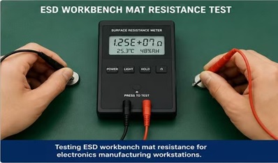
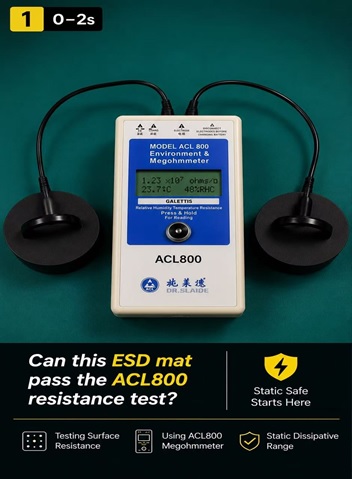
The industry added routine verification of the working surface with the proper resistance measurement instrument and defined the test method.
The calculation was made based on the facility’s ESD control plan and the reated test demand used for the chosen control items.
The testing process examined:
Resistance from the work surface to ground
Point-to-point resistance where applicable
- Grounding-cord condition
- Common-point-ground connections
- Snap connections
- Surface contamination
- Visible wear
- Cuts, burns, and damaged areas
800-meter ACL is used for selected surface resistance checks in the scope of the facility’s process. The instrument was not used as best for a complete compliance-verification plan. Test voltage, electrode configuration, environmental conditions, and measurement techniques were controlled according to the applicable method
The team found different problems:
- A mat that appeared undamaged had inconsistent readings
- One grounding cord was connected to an unsuitable point
- A metal bench frame had been assumed to be grounded but had not been verified
- Residue from an incorrect cleaning product affected a work surface
- A temporary rework bench had no documented grounding path
Each failed or questionable item was tagged, removed from service, or corrected before production resumed at that location.
Improving Flooring and Mobile Operations
production floor as well as operators who moved between storage racks, assembly areas, and testing stations. Previous management worked on wrist straps at fixed benches. Those methods did not fully address mobile handling.
- The team evaluated:
- ESD flooring condition
- Grounding connections
- Cleaning procedures
- Footwear compatibility
- Operator movement
- Carts and trolleys
- Mobile shelving
- Temporary floor coverings
The cleaning process was important. The floor used for static control does not work well if it becomes contaminated or maintained with products that leave an insulating residue.
The industry standardized approved cleaning materials and trained maintenance personnel. Flooring verification became part of the compliance schedule compared to an occasional response to an audit finding.
Using Ionization Where Grounding Was Not Enough
Not each material in the electronics process can be grounded.
Plastic housings, films, tapes, labels, and other insulative materials can retain electrostatic charge. Removing every insulator is not the best option normally in packaging, labeling, and certain assembly operations.
The factory found locations where main insulators were close enough to expose sensitive devices to create sudden risk.
Ionizers were installed or repositioned at selected locations, such as
- Rework stations
- Inspection points
- Packaging operations
Processes involving unavoidable insulative materials
The team ensured that each ionizer was best for the working distance and process conditions. Maintenance needs were documented, and performance checks were incorporated into the verification program.
The factory did not install ionizers indiscriminately. Ionization was used where the process assessment defined a need.
Controlling Packaging and Internal Transport
The project found that internal transport was one of the least controlled steps.
Boards were sometimes eliminated from a protected workstation and carried to testing in normal bins. Components got in protective packaging were occasionally shifted into unverified plastic containers for convenience.
The factory established rules for:
- Packaging ESD-sensitive items inside and outside the EPA
- Closing shielding bags correctly
- Avoiding unnecessary reuse of damaged packaging
- Labeling sensitive materials
- Moving assemblies between departments
- Storing work in progress
- Handling returned or rejected boards
Protective packaging was used based to where and how the item would be moved or stored. The same packaging solution was not automatically used for every stage.
Turning Training Into Observable Behavior
The original training program consisted mainly of presentation slides and an annual signature sheet.
The revised program based on practical features. Operators were shown:
- How charge can be generated
- Why damage may be invisible
- How to wear and test a wrist strap
- How to respond to a failed tester
- Why ordinary plastic trays can create risk
- How to identify an EPA
- Which materials are prohibited
- How to handle boards correctly
- When protective packaging must remain closed
- How to report damaged ESD control equipment
Supervisors got further training on audit response and corrective action.
Temporary workers, maintenance staff, cleaners, quality inspectors, and material handlers were added. The company defined that an ESD program fails when only production operators understand the rules.
Training effectiveness was defined through workplace observation and audit results—not simply attendance records.
Compliance-Verification Schedule
The central change was the use of a documented compliance-verification plan.
- The plan identified:
- What would be tested
- The applicable acceptance criteria
- The test method
- The instrument required
- Test frequency
- Responsible personnel
- Record location
- Corrective action for a failed result
The schedule covered control products such as:·
- Wrist straps:
- Footwear systems
- Work surfaces
- Flooring
- Grounding connections
- Ionizers
- Carts
- Shelving
- Packaging
- Garments where applicable
The team also established equipment calibration and maintenance requirements.
ANSI/ESD S20.20 offers a framework for developing and maintaining an ESD control program, with more information available at https://esdbest.com/, while IEC 61340-5-1:2024 offers requirements for an ESD control program for protecting electronic devices from electrostatic processes. The factory used the standards relevant to its customers, locations, and quality-system obligations, compared to treating a single checklist as universally sufficient.
Results
After [IMPLEMENTATION PERIOD], the factory compared the new results with the original baseline
Before the project
- Production volume:[BASELINE VOLUME]
- Confirmed or probable ESD-related defects: [BASELINE DEFECTS]
- Normalized defect rate:[BASELINE RATE]
- Workstation compliance rate: [BASELINE COMPLIANCE RATE]
- Wrist-strap test compliance: [BASELINE WRIST-STRAP RATE]
- ESD audit findings: [BASELINE AUDIT FINDINGS]
After the project
- Production volume: [POST-PROJECT VOLUME]
- Confirmed or probable ESD-related defects: [POST-PROJECT DEFECTS]
- Normalized defect rate: [POST-PROJECT RATE]
- Workstation compliance rate: [POST-PROJECT COMPLIANCE RATE]
- Wrist-strap test compliance: [POST-PROJECT WRIST-STRAP RATE]
- ESD audit findings: [POST-PROJECT AUDIT FINDINGS]
Using the normalized fault rate, the factory noted an 82% reduction in confirmed and probable ESD-related defects.
The calculation was:
Reduction percentage =
(Baseline normalized rate − Post-project normalized rate) ÷ Baseline normalized rate × 100
The company did not ask that the ESD program reduce every electronic failure. Soldering, component quality, design, contamination, mechanical stress, and other factors continued to need separate controls.
The result showed that disciplined ESD process management could substantially minimize one important type of manufacturing faults
What Produced the Improvement?
The factory concluded that no single buying accounted for the result. The greatest improvements came from 5 management decisions:
Measuring the process before replacing equipment
- Testing shows where real control faiure shown. that avoidfactor to replacement each mat or buying ionizers without understanding the exposure path.
Assigning ownership
- Each control product and verification process comes with a responsible person. Failed checks triggered a defined response.
Extending protection beyond the SMT line
- Receiving, inspection, rework, transport, and packaging were added in the program.
Connecting training to daily behavior
- Operators were trained for recognizing and respondingcontrol faiur comparing to just fulfilling an annual quiz.
Maintaining evidence
- Factor define that tested, when it was tested, that method used, and what occurred after a failure.
Lessons for Other Electronics Manufacturers
Manufacturers considering the same project should prevent beginning with a shopping list.
A more effective sequence is:
Find the ESD sensitivity of the products being handled.
- Map every point where sensitive items are exposed.
- Define the EPA and its boundaries.
- Establish personnel-grounding methods.
- Qualify the selected technical control items.
- Create a compliance-verification plan.
- Train everyone who enters or supports the controlled process.
- Record failures and corrective actions.
- Normalize quality data against production volume..
- Review the program whenever products, layouts or processes change.
A proper ESD program is not a collection of mats, wrist straps, gloves and warning signs. It is a documented system that connects risk assessment, technical features, verification and human behavior.
Conclusion
The factory’s 82% reduction in recorded ESD-related faults was obtained by making static control visible, measurable and accountable.
The project corrected grounding weaknesses, verified work surfaces, enhanced personnel controls, improved internal transport, managed important insulators and introduced a structured verification schedule.
Most importantly, the factory stopped handling ESD as an isolated technical fault owned by one engineer. It became part of the organization’s broader quality-management process.
For electronics manufacturers, that can be the high-transferable lesson: reliable ESD control does not begin with a product. It begins with a system.
About the Author
Rachel Zhong works with the technical team at ESDBEST, a manufacturer and supplier of static-control solutions for PCB assembly, electronics manufacturing, cleanrooms and industrial production environments.
The team’s work covers ESD work surfaces, personnel-grounding products, gloves, footwear, ionization, and workstation control.