Transistors are configured with chips, for which the terms “miniaturization” and “nanometers” are used. Transistors are considered building blocks of advanced electronics, such as digital circuits, because are considered building blocks of advanced electronics, such as digital circuits, since they are used as amplifiers and switches. In the form of discrete components, BJTs are commonly used semiconductor devices, with MOSFETs also being frequently utilized. The transfer HFE is compared to BJT that are in the same group.
For the selection of the required BJT according to our circuit, some factors must be considered, and here are some factors that are needed for making amplification circuits
What is hFE in a transistor?
It is known as DC gain or forward current transfer ratio, hFE, defined as the forward current gain that BJT gets during functioning at the time of active region circuits.
Most transistors work as amplifiers when configured in CE (Common Emitter) configuration; hFE applies to this amplification mode.
• The mathematical explanation for hFE is IC/IB, which is the ratio of the collector current to base current. So, for instance, if the hFE is 50, it shows that for every unit of base current, the collector current will be 50 times that. If IB is 1 mA, then the collector current will be 50 mA.
hFE can change according to some factors such as temperature and the transistor’s characteristics, so transistors of the same type and model usually have different DC gain values.
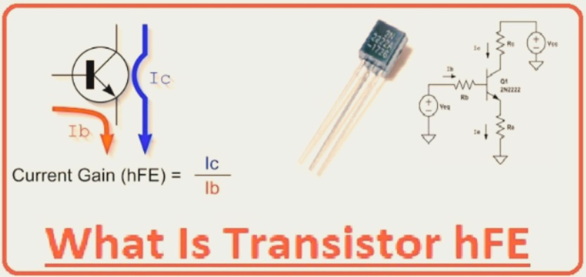
How hFE Works
To calculate the working of hFE, we consider the internal structure of a BJT as an example that comes with 3 doped semiconductor regions.
Amplification occurs in the active region of the transformer that occurs when the base-emitter junction is in forward-bias conditions and the base-collector junction is in reverse-bias conditions.
Base current regulates the working of the transistor, managing the majority of charge carriers over junctions.
• The high value of hFE shows the transistor controls larger collector current with small base current.
How to Find a Transistor’s hFE
The simple method is to forget the hFE of the transistor and check the datasheet reading that we can get from manufacturers. These datasheets provide the HFE range, not a specific value.
These range values are given since they can be different for the same type of transistors due to manufacturing tolerances and differences, which are difficult to control. It can also be based on the operating conditions, such as collector current and temperature.
To get a certain hFE value, we can measure the base current into the transistor and the collector current to substitute in the formula. Alternatively, you can use a multimeter to measure a transistor’s hFE directly.
That DC gain is helpful for understanding components’ working and working in circuits. Do not design amplification circuits that are based on hFE values to function because external conditions like temperature can alter them on the fly.
How To Calculate a Transistor’s hFE
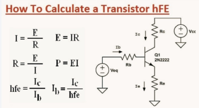
NPN and PNP amplification circuits
To get a real hFE value with calculations, set a circuit where the control base current (IB) is measured and the collector current (IC) is measured.
Measure the Base Current
For calculating base current, make a connection of known resistance with the transistor base pin and apply a known voltage across it. Calculate the current across this resistor or the base current using Ohm’s law by dividing the applied voltage by the known resistance.
Measure the Collector Current
By calculating base current, get the value of collector current to find values required for measuring hFE (IC/IB). Make a connection of other known resistance with the collector terminal in a series combination; get voltage losses over when the transistor is in the on state. Use Ohm’s law to calculate the collector current.
Calculate the hFE.
Use the two values above to get the forward current transfer ratio using IC/IB.
How To Measure a Transistor’s hFE Using a Multimeter
Calculating the hFE value applies a multimeter easily since no resistor is needed. Use common types of transistors such as 2N2369 or S8050 NPN types, get the collector, base, and emitter pins using their pinout diagrams, then insert them into the multimeter’s transistor port. Ensure you use the NPN side for these two and the PNP side if measuring the hFE for PNP transistors.
A digital multimeter with hFE measurement functionality for NPN and PNP transistors
Set the multimeter to the hFE position using the middle selector knob and read the hFE value on the display.’
Different Current Gain States
Transistors function in 3 regions, and each offers different current gain.
Active/Linear Region
transistor works in the amplifier region, where the base-emitter junction is forward biased and base-collector are in reverse biased. The current gain in that region will be hFE, or beta.
Saturation Region
In this region, both junctions are forward-biased, and the transistor is full on, providing high current to flow. When base current increases, collector current moves linearly until it reaches a saturation point where it can’t rise further.
Cut-Off Region
The transistor functions as an off switch in the cut-off region since both junctions are reverse-biased. So the current gain is zero since there are no base and collector currents.
Factors Influencing Transistor hFE
The forward current transfer ratio in the CE configuration can be based on these factors.
Temperature:
When the internal temperature of the transistor is high, hFE becomes lower, which shows amplification features going down. That occurs since there is an increase in the concentration of minority charge carriers, which affect/repel the flow of majority charge carriers.
Collector Current:
hFE increases as collector current increases but gives a non-linear ratio. After getting a peak, HFE starts decreasing.
Manufacturing Variations:
Manufacturing process differences and tolerances provide transistor smoothness from the same plant, and manufacturing lines come with different HFE values.
These results are due to small changes in doping levels that affect minority and majority charge carriers of the BJT. Differences in base thickness also vary the charge carrier ratio that affects HFE.
Collector-Emitter Voltage:
VCE has an effect on DC gain, although its impact is minimal.
Signal Frequency:
With high switching frequency, the transit time of charge carriers is not longer compared to the signal period, making the transistor work well. This lowers its current gain.
Aging:
Transistors and semiconductors degrade with time, especially when used for longer at high temperatures; voltage and current degrade inside. Therefore, the hFE value reduces with time.
Role of hFE in Transistors
hFE is the main factor for transistors and their electronic circuits.
Signal Amplification
Transistors are commonly used for amplifier circuits, and HFE means the amplification features of these components of circuits. High hFe means good signal amplification properties.
Transistor Biasing
Biasing structure based on the hFE value to calculate the required base current for a given collector current to ensure accurate stability and operation at different temperatures.
Circuit Design
For the CE configuration, amplifier gain has a direct proportional relation with the hFE value. Therefore, this value can help define how to design the circuit, for instance, by helping to calculate the base resistor value.
Transistor Switching
Digital logic circuits use transistors as switches, and hFE values are used for measuring the required control signal base current for operating the switch into saturation mode.
Other roles include:
Creating Feedback Networks: To design control systems
Performance Optimization: Useful for optimizing filters, oscillators, and other analog circuits
Transistor hFE vs. Other Types of Transistor Gains
Besides, the HFE transistor gives different gain types, and here’s how they compare.
hFE or Beta (β)
As defined before, hFE is the DC current gain in a transistor circuit made in CE configuration. The beta symbol β is used for NPN transistors, while β’ is used for PNP transistors, and generally, the hFE value ranges from 20 to 1000 for general-purpose transistors.
hfe
For all small letters, hfe shows ac current gain that is defined for a certain frequency. That gain is the same as the HFE calculated through changing voltage and current conditions.
Alpha ( α)
Alpha is the DC current gain calculated from BJT for the common base configuration. whose value is close to one, and the formula is the ratio of DC collector current to DC emitter current (IE), or IC/IE.
Voltage Gain (Av)
The output-to-input voltage ratio is an important factor for some transistor amplifier circuits, and the ratio is voltage gain, or Av.
Power Gain (Ap)
For power applications, such as power amplifiers, the output-to-input power ratio is the main factor, and this ratio is known as the power gain.
Conclusion
As we see, understanding HFE is an important factor for using BJT in the circuit and in the amplification process. That ratio is the main factor for biassing, switching, and circuit optimisation since it helps to find the required base current for using the control to turn on the transistor. When you know the required activation current, you can measure the suitable resistor to use at the base.
So whether you use PNP or NPN BJTs, we refer to measuring hFE using known resistances or a multimeter to find the circuit’s design and component values.