New battery chemistries are used for the invention of electric cars, and they store energy from renewable sources. Charging basics are the same: constant current, constant voltage, and auto cut-off.
3 commonly used charger types use one basic point for pushing current into battery cells and increasing voltage to the designed full level. For understanding the complete charging process, we will cover three basics in detail, also 3 common charger types to see their advantages
Battery Charging Parameter Fundamentals
All battery charging circuits use one of these basics or fundamentals
Constant Current (CC)
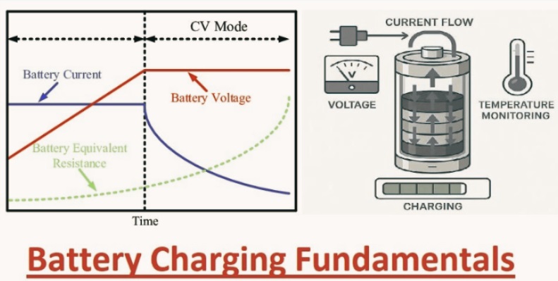
As the name says, constant current charging uses a charging battery with a fixed current that is maintained through voltage changes. This provides high-speed charging, so we know when to connect the plug to the phone.
CC operates until the battery gets a predefined voltage value; after that, CV starts.
Suppose a circuit that needed one ampere of current for recharging a battery with 1.25 V as a reference voltage for an LM317 voltage regulator.
A constant current electrical circuit
The circuit needed a resistor for current regulation, and we can get the value with the equation R=V/I.
R=1.25V/1A, which is 1.25 ohms. But since there’s no 1.25-ohm resistor, we’ll use a 1.5-ohm resistor, which is the closest one.
If the power supply of dcsoruce like solar panels, there is no need of a step-down transformer, rectifier, or capacitors.
Constant Voltage (CV)
Through a constant voltage circuit, the voltage output is constant for the charging process, and it is achieved with two resistor connections with an LM317 voltage regulator.
A constant-voltage electrical circuit
Let’s say we want the output voltage to be 8.4V. The R1 value should be less than 1,000 ohms, such as 560 ohms.
Using the formula Vout = Vref (1+R2/R1), we can determine the value of the second resistor.
8.4 = 1.25V (1+R2/560)
R2 = 3300 ohms (3.3 kilo-ohms)
You can use any resistor combination that outputs around 8.4V in this setup.
• A different battery charging system uses CC and CV for making a hybrid system that operates CC first and then switches to CV when the voltage gets a threshold value.
CC defines the charging time, while CV affects the capacity utilization. The charging process is considered complete when the current levels off and full battery capacity is attained.
Auto Cut-Off
Some batteries use an auto-cut-off circuit for circuit protection from overcharging that affects cells over time.
An auto-cut-off electrical circuit for battery charging
• In this circuit configuration, we can set power movement into the voltage regulator ADJ pin using the variable resistor, which then changes the output voltage.
When the battery is fully charged, the zener diode generates reverse voltage that flows in the BD139 transistor’s base. This turns on the switch, which connects the ADJ pin to the ground, cuts off the voltage output from the regulator, turns on the red LED, and turns off the green LED.
Battery Charging Circuit Types
These 3 charging circuit types can use either of the charging parameter fundamentals discussed above.
Linear Charger
Linear battery chargers are a basic type since they use fewer components; the main component is a linear regulator, such as the LM317. They are also low cost, take up little space, and generate little noise (radiated and conducted emissions) since they don’t apply switching and filtering functions.
But this charger is not ineffective; normally it is for high-power projects since disspiates high power that releases in heat form.
The circuit should lose AC voltage down to battery voltage that causes high losses.
Reducing charging current also minimizes losses but increases charging time. We can use either heat or extra charging time according to the application.
The MAX1898 IC is more effective than the LM317 at these linear charging operations because it features a pre-qualification state that reduces the charging current for any battery voltage that is less than 2.5V.
A linear charging circuit using the MAX1898 IC
So high losses occur when using the above circuit occur when the load is larger than 2.5 V, and the input voltage has the highest level.
Switch-Mode Charger
Read Also 36V Lithium Battery: Types, Capacities, and Right Option
Switch-mode chargers are more effective than linear modules for high-power projects since the power dissipation factor is low. Normally, that factor is lower than one watt over the complete battery voltage range during charging, which works well for different input voltages.
With that switch-mode circuit designed, easily for charging as many as 4-series cells concurrently at up to 4A.
That efficiency comes at the result of cost. Switch-mode chargers are larger in size and have a more complex design compared to linear modules since they need multiple components.
such as, when using the MAX1737 controller, there is an external buck converter, which comprises the following.
Passive low-frequency bandpass LC filter
Switch (usually MOSFET)
Diode
These components needed more PCB space and made the charger costlier.
A switch-mode charging circuit using the MAX1737 IC (note the external buck converter)
The switching process also produces high EMI, and the filter inductor generates radiation noise. But the MAX1737 has a 300 kHz PWM oscillator to reduce this noise. The IC also features a safety timer to control overcharging and continuous battery monitoring (temperature and voltage) for safe charging.
Pulse Charger
Pulse chargers combine features of switch-mode and linear chargers. They function linearly when the battery voltage is low since their pass transistor remains on and conducts input current directly to charge the cells.
• The charger also functions accurately as a switch-mode charger circuit since it pulses input current when the battery voltage gets to the regulation point.
that pulsing helps to provide the required charging current, which regulates voltage at a certain value. A nonlinear function at this point minimizes power losses and reduces high heat production.
Since the circuit doesn’t need an LC filter, it is less complicated than switch-mode circuits and rivals the simplicity of the linear type.
A pulse charging circuit using the MAX1736
That circuit comes with special features like needing a proper current-limited voltage source at the power input. The current limiting level for pulse charging chips such as MAX1736 is costly and not universally available.
Different Charger Types summary
| Charger Type | Pros | Cons | Applications |
| Linear | Simple circuits Cheap to make Generate little EMI and radiation noise | Highly inefficient, especially in high-power applications | PDAs Self-charging battery packs Cell phones Cradle chargers Single-cell lithium-powered portables |
| Switch-Mode | Highly efficient for high-power applications Easy to scale | Generates a lot of EMI and radiation noise Large, expensive, and complex circuit | Notebook chargers Lithium-ion battery packs Desktop cradle chargers Hand-held instruments |
| Pulse | Highly efficient for both low and high-power applications Simple circuit | Requires an accurate current-limited voltage source | Wireless handsets PDAs Digital cameras Self-charging battery packs Cradle chargers |
Future impact in Battery Charging Technology
Soft Switching:
Future switch: The charger switches to soft switching to reduce EMI and power losses, improving efficiency and enhancing working performance.
Switching To Active AC-DC Rectification:
Diodes provide forward-bias losses of circuits that can be minimized with replacement with active semiconductor switches or bridgeless topologies.
Leveraging SiC and GaN to Accelerate Switching:
Silicon carbide and gallium nitride give high-speed switching and reduce losses, which causes shrinking of heatsinks and passive magnetic components, resulting in smaller chargers.
Advanced Cooling Mechanisms:
Battery chargers also release losses in heat form irrespective of efficiency. Advanced passive, liquid-based, or fan-operating cooling systems release heat quickly so components work well and last longer.
Integrated Systems to Simplify Designs:
Integrated systems are compact, low-cost, and low-complicated compared to making circuits with separate components. Future chargers can use buck converters and different parts built into the chip to achieve these benefits.
Conclusion
As we discussed, linear, switch-mode, and pulse chargers use basic AOVE and are different. But their final results are the same.
We can use different battery charging integrated circuits for these operations or use complete chargers that are applied for different operations, like solar charging, or handle defined battery chemistries, such as lithium-ion. The latter can minimize the time to market for your product, but either option can work.