The NE555N timer integrated circuit, which has stable control, has features to provide oscillation or delays. For the time delay operation mode, time is accurately regulated by employing a capacitor and a resistor. Its operation as an oscillator helps to control the free operating frequency and duty cycles, regulated with 2 external resistors and employing a single capacitor.
In this tutorial, we will cover detailed features, circuits, and relevant factors of NE555 timers. So let’s get started.
What is the NE555N timer?
- NE555N monolithic timing circuit controller provides time delays or oscillations. For time delay functions, time is regulated with an external resistor and a capacitor.
- For getting frequency and duty cycle for dependable oscillator operation, two external resistors and one capacitor are used.
- The circuit started and reset with the help of descending signals, and the output supply or drain was about 200 mA.
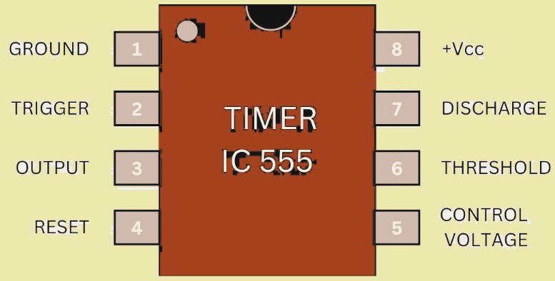
- The NE555 is part of the NE55 series, which is a timing circuit that regulates time with an oscillating circuit. It has 8-pin DIP packages made with plastic structures.
- The NE555N has features to manage about 200 mA of output current, so it is employed for different applications. Its design makes easy connections with circuits and also with different projects.
- Its design makes it best for industrial operations, making it a simple design.
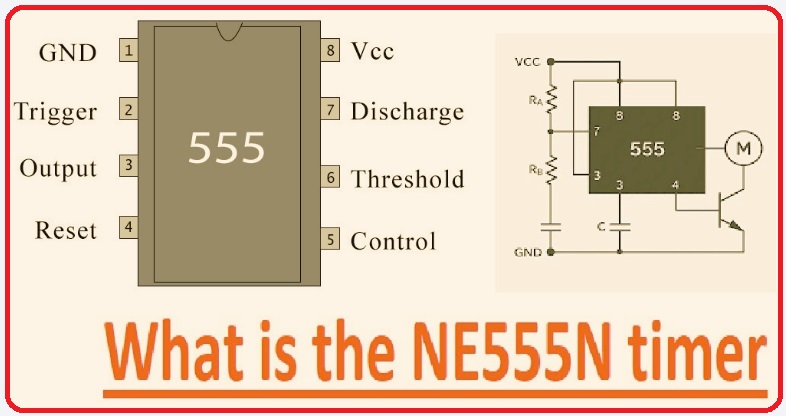
Pin of the NE555N Timer
| Pin# | Pin Name | Definition | Explanation |
| 1 | GND | 0V | It is connected with negative point of the power supply. |
| 2 | TRIG | Trigger Input | if voltage of pin is less than 1/3 of V_CC, it operates the timing interval. For monostable mode, a low pulse of TRIG start output pulse |
| 3 | OUT | Output pin | The output pin give200ma through sourcing or sinking with ground. output becomes high or low according to 555 conditons. |
| 4 | RESET | Active-low Reset input | if voltate of this pin is less than ~0.7 V, resets the timing cycle. |
| 5 | CTRL/CV/CONT | Control Voltage input | This pin bypassed ground through a 0.01 µF capacitor for stablizing threshold. The external voltage of pin 5 is given to modulate timing |
| 6 | THRES | Threshold input | if voltage of the pin is higher than 2/3 of VCC, it resulting 555 internal comparator for resetting the output |
| 7 | DISCH | Discharge output | if output of the timer is low that pin collector pin 7 is connected to ground. |
| 8 | 𝑉𝑐𝑐 | Positive Power Supply | Power voltage of integrated circuit with 4.5 to 15v according to variation, it is recommended a 0.1uF decoupling capacitor for noise filter |
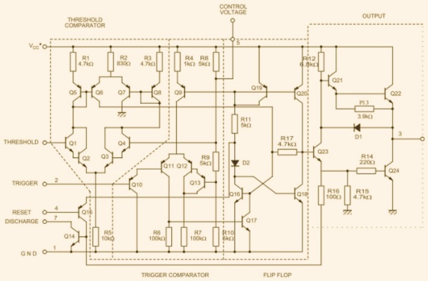
How Does a NE555N Timer Work?
The NE555N timer IC is created with transistors, comparators, and flip-flops. This IC operates with 3 operating modes. The NE555 uses the 555 timer IC with two functions, monostable and astable. These two modes cause operations with 555 timer integrated circuits.
The RC timer circuit comes with a resistor and capacitor that are designed with the capacitor and resistor making a timing system through the connection of the IC threshold and trigger pins. This system defines timing features of integrated circuits.
3 operating modes of 555 timer ICs are
Monostable Mode
- The 555 timer generated single fixed-width pulses since it operated as a one-shot multivibrator. for idle cirucit there is an output low and an external capacitor uncharged. So when a negative trigger pulse is sent towards pin 2, output pin 3 becomes high, and the capacitor starts charging with the resistor.
- With that discharge transistor of pin 7 off, the resulting capacitor starts charging with the resistor.
- So the output is high until the capacitor voltage gets.
- So output becomes low again, and the capacitor gets discharged through pin 7 to ground.
- The timer is not considered a new trigger signal till the completed cycle, resulting in the production of one pulse in a single trigger.
- Output high pulse time in monostable mode defined with RC timing components. so pulse width T is
𝑇 =1.1 ×𝑅 ×𝐶
- This equation shows to make single shot timer with R and C for adding the required delay.
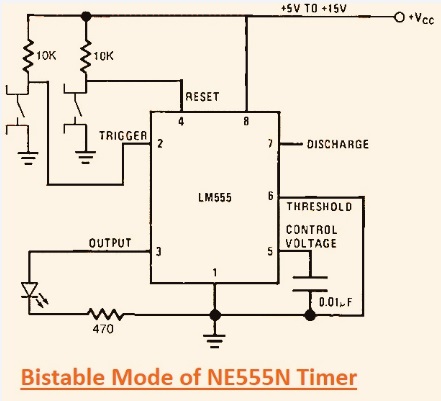
Bistable Mode of NE555N Timer
- In bistable 555 timer mode, the latch output is in a high or low state until the external trigger condition varies. Here we have made a bistable circuit diagram with an LED to define the 555 timer bistable mode.
- In this mode, when we apply force on the button on pin 2, the timer is in a high state, and the LED turns on. If we click the reset button at pin4, the LED turns off and remains in this state.
- For practical applications, pin 7 is disconnected, and pin 6 is connected with ground, managing voltage at that pin to reach the 2/3 Vcc threshold that resets the output.
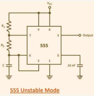
555 Unstable Mode
- Astable mode makes the 555 timer a continuous square wave generator that is a multivibrator. In this design, frequency and duty cycle signals are defined with resistors R1 and R2 and a capacitor C.
- Equations for charging and discharging time are t1 = 0.693 × (R1 + R2) × C and t2 = 0.693 × R2 × C, and the frequency is mentioned through
- f = 1.44 / ((R1 + 2 × R2) × C).
- Setting R1, R2, and C causes accurate control of the signal feature with the LED blinking, resulting in the production of an audio signal.
- Through designing and fine-tuning these features, make practical features for the output signal’s shape according to project features.
Technical Specifications
| Features | Details |
| Operating Modes | Astable, Monostable |
| Number of Timers | 1 |
| Number of Channels | 1 |
| Logic Function Number | 555 |
| Device Marking | 555 |
| Chip Marking | 555 |
| Frequency | 500 kHz |
| Maximum Operating Frequency | 0.5 MHz |
| Clock, External Input | No |
| Power Supply Voltage Range | 4.5 V – 16 V |
| Minimum Power Supply Voltage | 4.5 V |
| Maximum Power Supply Voltage | 16 V |
| Package Format | DIP |
| Packaging Type | DIP |
| Pin Count | 8 |
| Surface Mount Device | Through-hole mounting |
| Operating Temperature Range | 0°C to +70°C |
| Working Temperature | 0°C – 70°C |
| Temperature Range | Commercial |
| SVHC (Substances of Very High Concern) | No SVHC as of 20-Jun-2011 |
Supply Voltage
- The 555 timer effectively operated with a voltage value of +5V to +18V. This voltage range helps to employ different projects. Operators use power supplies according to voltage level requirements for providing stable IC functions.
Load current
- 555 timers can handle 200 milliampere load current, helping to provide medium power loads like motors or LED light strips. This high-current feature reduces the use of power amplifiers, making circuit design easy and minimizing extra components.
Timing Range and Frequency Setting
- External resistor and capacitor connected for set timing from microseconds to minutes through a frequency setting range of about hundreds of kilohertz. This design helps the operator to tune devices at certain requirements, like configuration with a certain audio video videosignal for signal generators or decorative lights.
High current output:
- The output pin offers 200 mA to operating TTL logic circuits. That is a helpful factor for minimizing auxiliary parts like extra transistors or repeaters, making the design simple and effective for low-cost options.
Stable Temperature
- The 555 timer comes with a stable rate of 50 ppm for a single degree centigrade and offers accurate time features with different temperature ranges. It offers accurate features for different environments, like indoor or outdoor in different conditions.
Duty Cycle setting
- 555 timer variable duty cycle enhances output signal control and is best for generating signals for PWM projects. Setting the duty cycle provides accurate control for light intensity and motor speed, helping to accurately manage device operations.
NE555N Equivalents
| Part Number | Details |
| NE555D | 1 Func, PDSO8, SOP-8 BIPolar. |
| LM555CMX | IC PULSE; RECTANGULAR. TIMER. PDSO8, SOIC-8. |
| SA555D | 1 Func, PDSO8, BIPolar. SOP-8 |
| ICM7555CD-T | IC PULSE. 0.5 MHz.PLASTIC, MS-012, TIMER. PDSO8, 3.90 MM. SOT96-1, SOP-8, Analog Waveform Generation Function |
| TLC555QDR | 250-pA. 2.1-MHz, Low-Pow/er Timer 8-SOIC -40 to 125 |
| MC1455BD | PULSE; RECTANGULAR. TIMER. PLASTIC PDSO8.. SO-8 |
| ICM7555ID | ICM7555IDSOT96-1 |
| NE555DT | PULSE; RECTANGULAR. TIMER. PDSO8, 0.5MHz MICRO, PLASTIC, SO-8 |
| ICM7555CD | ICM7555CDSOT96-1 |
| TLC555QDREP | PULSE; RECTANGULAR. 1.2MHz, TIMER. PDSO8, GREEN. PLASTIC, SOP-8 |
Infrared Blocker Using 555 Timer
- 555 timer used for making an infrared interceptor that is used for forsignalblock of a TV remote control. The 555 timer, operated in astable mode, helps to release a high frequency of 38 kHz with a 60 percent duty cycle, fulfill the required frequency of the TV remote signal, and block it.
The circuit diagram of the 555 timer tester is made, where
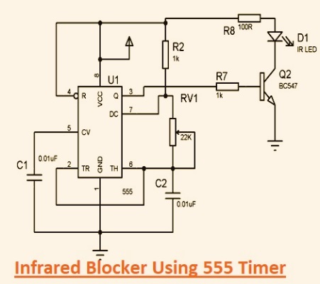
Pin 1 is connected with ground for a stable circuit design. Pin 2 and pin 6 are cycled with each other; that is a standard feature for non-stable mode to offer required oscillations.
Pin 3 is connected with the base of an NPN transistor operated as a switch that regulates IR diode activation.
Pin 4 and pin 7 are connected through one kilo-ohm and come with a reset function for avoiding oscillations from mistakenly stopping.
Pin 5 is connected with the ground through a 0.01 uF capacitor for stability control voltage and reduces output variations resulting from power supply changes.
Pin 8 offers the needed voltage to the circuit for the power supply.
The BC547 transistor emitter is configured with ground and the collector with a 6V DC supply and configured through a 100-ohm resistor and an infrared diode.
This circuit assembly helps the transistor to operate when the 555 timer output is high, operating the infrared diode to release light at a 38 kHz frequency.
With proper assembly and circuit calibration, accurate settings with resistors and capacitors help to transmit frequency for accurate configuration to the remote.
with minor frequency differences resulting in signal blocking. Accurate connection and transistor wiring and infrared diode cause accurate operations.
NE555N timer Schematic Diagram
NE555N timer Applications
Correct Timing
- The NE555 timer has features for providing accurate timing calculations for applications where timing accuracy is needed for industrial applications.
- These features make it preferable for different environmental conditions for constant laboratory settings in different calculations.
Adaptive pulse production
- This timer has features for producing pulses at different time intervals and widths, resulting in use for signal processing and the telecom sector. Using NE555N in different pulse frequencies offers digital circuit configurations.
- These features are employed for making clocks and waveform generators where electronic signals are needed. Its features for adapting pulse features for fulfilling some circuit requirements enhance its usage features, and it’s also part of making circuit design.
Sequential Timing
- The NE555N’s capacity for making timing sequences is an important feature for an automation system. These sequences operate functions that need accurate timing, like conveyor belt design systems and light control.
- We can define timer dependability features and easy connection properly through providing a high-functioning system that minimizes oversight.
Time Delay Features
- Time delay is a main feature of the NE555N that provides the main features for handling power and safety circuits. It can add delay and cause system overloads through the staggering activation of features in different projects.
Conclusion
The 555 timer integrated circuit is an important part of an electronic circuit, offering good features and a versatile design. It comes in different modes, like monostable, bistable, or astable, and it is set through external components to fulfill design requirements. It has different power supply ranges, large current management features, and stable temperature, which helps to use it for different conditions.
Its pin design and working features help to design an accurate circuit. Buzzer timing control and infrared blockers are common circuits of this timer.
Frequently Asked Questions [FAQ]
What is the voltage value of the 555 timer?
- The 555 timer works at different voltage values. normally operate with 4.5V to 15V. In low-voltage projects, it comes with low-voltage features like the 7555 that operate for 2 volts. Choosing the operating voltage, it helps that the voltage source has a stable design to prevent the operation performance of the timer.
How to check if the 555 timer is working well?
- To find that the 555 timer is operating well, these points work.
- Multimeter employees for measuring voltage between the power pin and the ground pin of the timer to make sure it has a normal voltage range.
- Check the output pin voltage; if the 555 timer is operating in a stable way, the voltage pin will vary in a periodic way. oscilloscope use for finding these variations or LED light with a resistor in series through the output pin to determine LED flickering
Is the 555 timer analog or digital?
- The 555 timer is an analog component. Either it is used for digital projects like producing time intervals, or its design and working features are set on analog operations and the output is regulated with the charge and discharge of a capacitor.


