
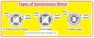
Hello friends, I hope all of you are fine. In today’s tutorial, we are going to have a look at types of synchronous motors. In the electrical system there are 2 main types of mostly used motors: the first one is the synchronous motor, and the second one is the induction motor. The main difference in these 2 motors is that the induction motor is self-starting, while the synchronous motor is not self-starting; it needs special arrangements for starting its operation. In our power system, the most used motor is the synchronous motor, as it can operate at lagging, leading, and unity power factors.
In today’s post, we will have a look at its different types, their working, applications, and circuits. So let’s get started with types of synchronous motors.
Types of Synchronous Motor
There are 2 main categories of synchronous motors: the first one is non-excited, and the second one is DC-excited motors.
These categories of motors are defined according to the magnetization behavior of the synchronous motor.
Let’s discuss these categories in detail and their subcategories.
Non-Excited Synchronous Motors
The rotor of these motors is constructed by steel. During its rotation at synchronous speed, it follows the synchronous rotating field in different steps; due to this, it provides a constant field.
Due to the field interaction of the stator with the rotor, it becomes an electromagnet, and it has north and south poles that interact with the stator field poles; in this way, the rotor moves.
The rotor is made from material that has a high value for magnetization and demagnetization, meaning its retentivity is high.
These non-excited motors are further divided into three main types that are described here.
Reluctance motors
Hysteresis motors
Permanent-magnet motors
Let’s discuss these motors in detail.
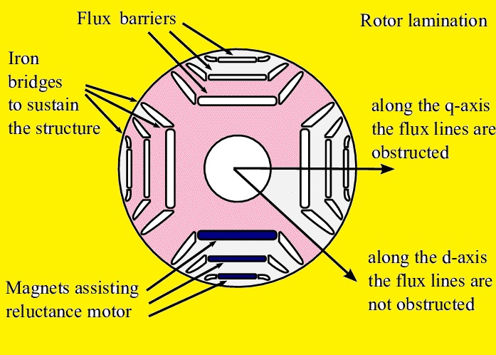
Reluctance Synchronous Motors
The rotor of these motors is constructed by steel that have different poles, like salient rotor motors.
Characteristically, there are fewer rotor than stator poles to lessen torque ripple (it is a factor that occurs in numerous electrical motor structures, causing increments and decrement in output torque as the shaft of the rotor revolves) and to stop the poles from such alignment that does not produce torque.
The magnitude of the air gap in the magnetic circuitry and reluctance is lowest when the poles are in a straight line with the revolving field of the stator and surges with the angle among them.
This makes a torque, dragging the rotor into alignment with the nearby pole of the stator’s rotating field.
So at synchronous speed, the rotor is locked up with the revolving field of the static part of the motor.
It cannot initiate operation of the motor due to these poles of the rotor being wound with the squirrel cage windings inserted in them to deliver torque lower than synchronous speed.
The motors initiate as induction motors until they get synchronous speed when the rotor gets locked with the rotating field of the rotor.
The rating of these motors starts from a few HP to almost twenty-two kilowatts.
A lower-rated reluctance motor has less value of torque and is mostly used in different instrumentation applications.
Reasonable torque: higher-rated motors use a squirrel cage structure with jagged rotors.
When these motors are connected to a variable-frequency power supply, all motors in the scheme can be regulated at a similar speed.
The frequency of the supply defines the rotating speed of the motor.
Hysteresis synchronous motors
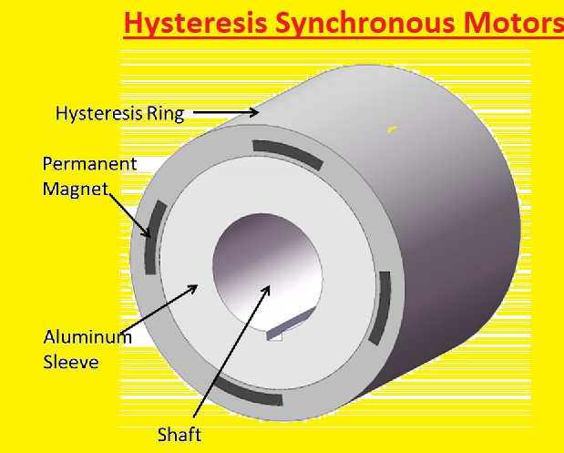
The rotor of this motor is constructed by high-coercive steel in a cylindrical shape. Coercive material is such that it has a high value of magnetization and then a larger value demagnetization field in the opposite direction.
Due to the field of the stator that is revolving, it produces a voltage in the rotor and field in opposite directions.
Due to hysteresis (it is the energy required to magnetize and demagnetize any material), the angle of the magnetization lags the field provided at the stator.
The consequence of this is that the axis of the field produced at the rotor lags the field at the stator and angle, creating a torque as the rotor attempts to follow the revolving speed of the rotor.
As the speed of the rotor is less than the speed of the stator field, which is known as synchronous speed, every element of the rotor bears a retrogressive field at a frequency that energizes it around its hysteresis loop that makes the rotor field lag and generate torque.
At the rotor, there are two poles of less reluctance bar construction. As the rotor tries to reach the rotating field of a stator and slip becomes 0, this magnetizes and aligns the stator’s field, making the rotor locked with the field of the stator.
A main benefit of the hysteresis motor is that as the lag angle does not depend on speed, it produces an initial point to get synchronous speed.
Due to this feature, it is a self-starting motor, so there is no need for a special circuit for starting, though numerous schemes have a squirrel-cage winding arrangement fixed in the rotor to deliver additional torque at the start of the motor.
Permanent-Magnet Synchronous Motors
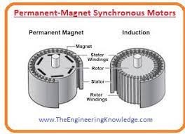
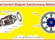
The rotor of this motor consists of a permanent magnet assembled with the steel that provides a continuous field without any interruption.
At the stator, an alternating current supply is connected to produce a rotating field.
When the rotor rotates at synchronous speed, its permanent magnet locks up with the rotating field of the stator.
These motors are similar to brushless direct current motors.
As the rotor is a permanent magnet, it provides a constant field; due to this, induction windings cannot be connected with these motors for starting.
Instead, these motors need such a source that has a variable frequency.
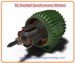
DC-Excited Synchronous Motors
- The rating of this motor is larger than one HP or one KW. The external direct current source is connected to the rotor of these motors for excitation.
- This direct current source is connected to the motor by a slip ring by rectifier circuit for rectification of the supply.
- The direct current at the rotor can be provided by 2 ways first one is by connecting an external source, and second is by attaching a direct current generator with the shaft of the rotor.
so friends, these are the types of synchronous motors that are described in this tutorial. If you still have any queries, please ask in the comments. See you in the next tutorial.
- I also have written some related articles you can also read them are listed here.I
- Introduction to Synchronous Motor
- Synchronous Motor Torque-Speed Characteristic Curve
- Synchronous Motor Starting Method
- What is Synchronous Condenser (Capacitor)
- Synchronous Motor Power Correction.
- Types of Synchronous Motor
- Effect of Field Current Changes on a Synchronous Motor.

well written and good work…
V goood
Excellent information to note. Thanks very much for the information.
thanks for appreciation
Hello! I’m at work browsing your blog from my new iphone! Just wanted to say I love reading your blog and look forward to all your posts! Keep up the excellent work!